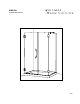
M-DP93X 06.
Custom Order FINISH 11- Bright Chrome 12- Bright Brass 25- Brushed Nickel 29- Oil Rubbed Bronze GLASS 40- Clear Please keep this manual and product code number for future reference and to order replacement parts if necessary.
INSTRUCTION MANUAL ● Table of Contents MODEL NUMBER............................................... 2 GENERAL INSTRUCTIONS .................................... 3 INSTALLATION OVER CERAMIC TILES ....................... 3 NOTICE ......................................................... 3 CARE FOR YOUR FRAMELESS SHOWER DOOR ............. 3 PARTS LISTING................................................. 4 PROVIDED HARDWARE........................................ 5 REQUIRED TOOLS AND MATERIALS ...................
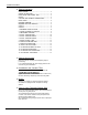
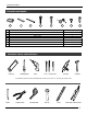
INSTRUCTION MANUAL PARTS LISTING 5 6 8 4 1 2 7 3a 9 3b 3c 10 12 13 ITEM 11 PARTS QTY 1 PIVOT SUPPORT BAR 1 2 WALL JAMB- TEMPLATE 1 3a RETURN PANEL 1 3b EXPANDER 1 3c GASKET 1 4 CORNER CLIP 2 5 SIDE PANEL WITH CORNER CLIP 1 6 MAGNETIC DOOR GASKET 2 7 DOOR PANEL 1 8 SQUARE WALL-MOUNT HINGE 2 9 SIDE PANEL GASKET 1 10 CURVED HANDLE 1 11 BOTTOM GLASS CLIP 1 12 BOTTOM DOOR GASKET 1 13 THRESHOLD 1 *on page #6 4
INSTRUCTION MANUAL PROVIDED HARDWARE 14 15 16 17 18 19 20 21 14 SPACING BLOCKS 2 15 CLEAR SETTING BLOCK 2 16 CLEAR SETTING BLOCK 2 17 WALL PLUG 4 18 SELF DRILLING SCREW #8 - 1 1/4 3 19 SCREW CAP 4 20 SELF DRILLING / SCREW #8 - 3/8 3 21 FLAT HEAD SCREW #6 - 3/4 2 REQUIRED TOOLS AND MATERIALS * HACKSAW SCREWDRIVERS DRILL 1/4˝& 1/8˝ DRILL BITS SILICONE HAMMER * If the shower panels are to be assembled on ceramic tiles, use a 1/4˝ drill bit for ceramic tiles.
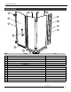
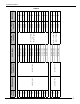
(30 3/16” x 75") (31 3/16” x 75") (32 3/16” x 75") (29 3/16” x 75") (30 3/16” x 75") 52 53 54 55 56 58 (32 3/16” x 75") (31 3/16” x 75") (29 3/16” x 75") 51 57 (28 3/16” x 75") 50 (24 3/8" X 70") (27 3/16” x 75") 49 (32 5/8" X 70") (25 3/16” x 75") 47 (26 3/16” x 75") (24 3/16” x 75") 46 (20 7/16" X 70") (23 3/16” x 75") 45 (32 5/8" X 70") (22 3/16” x 75") 44 48 (21 3/16” x 75") DOOR PANEL 43 CORNER CLIP SIDE PANEL WITH (20 3/16” x 75") RETURN PANEL 42 (PXKRP*) MODEL B
INSTRUCTION MANUAL WALL TO HINGES X CHART B DIMENSIONS MODEL X Y Y WALL TO CENTER OF RETURN PANEL 42 41 13/16" 43 42 13/16" 44 43 13/16" 45 44 13/16" 46 45 13/16" 47 46 13/16" 48 33 3/4" 47 13/16" 49 48 13/16" 50 49 13/16" 51 50 13/16" 52 51 13/16" 53 52 13/16" 54 53 13/16" 55 54 11/16" 56 57 58 33 3/4" 55 11/16" 56 11/16" 57 11/16" 7
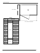
INSTRUCTION MANUAL 1 DETERMINE HINGES LOCATION. LEFT CONFIGURATION 1A RIGHT CONFIGURATION USE THE WALL JAMB (#2) AS TEMPLATE TO MARK DRILLING LOCATIONS FOR WALL-MOUNTED HINGES. WALL-MOUNTED HINGES MUST BE SUPPORTED AND FASTENED INTO A STUD FRAMING. x y 1A. Determine on which side the hinges will be mounted. 1B 1B. Trace the hinge locations by referring to the "x" dimension on page 7. Run it up the wall. 1C.
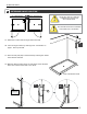
INSTRUCTION MANUAL 2 FASTEN THE HINGES TO THE WALL. 8 NEVER PLACE THE GLASS DIRECTLY ON THE FLOOR. 2A. Fasten the hinges (#8) to the wall as illustrated. INTERIOR SHOWER SIDE 3 3A. PREASSEMBLE THE DOOR. INTERIOR SHOWER SIDE 6 Temporarily insert the bottom door gasket (#13) under the door panel. 12 APPROX. 1/2" LÈVRE LIP 7 6 15 7 3B. Install the 2 spacing blocks (#15) onto the bottom lip of the gasket. FINAL RESULT 7 3C.
INSTRUCTION MANUAL 4 INSTALL THE DOOR PANEL. 7 IT IS BEST TO HAVE 2 PEOPLE WORKING ON THIS STEP. INTERIOR SHOWER SIDE 4A 4A. Place the door assembly on the shower threshold and level it. 4B. Fasten the hinges as illustrated using the Allen key. 4B 13 15 4C. Remove the leveling blocks (#15) and the bottom door gasket. 5 4C INSTALL THE DOOR HANDLE. 5A. Install the curved handle (#10) as illustrated.
INSTRUCTION MANUAL 6 INSTALL THE DOOR GASKETS. 5 6 12 6B 6A 6 45º INTERIOR SHOWER SIDE 12 9 RIGID PART 6A. With the cutting pliers, trim the top of the magnetic gasket (#6) as illustrated. 6B. Project the 45° magnetic gasket surface on to the bottom door gasket (#13). Trim the bottom door gasket. ± 1/8" ± 5/8" 6C ± 1/2" SUGGESTED TRIMMING 6C. Open the door and clean the door panel surface on which the door side gasket (#9) will be placed. Align it to the sure it is oriented as illustrated.
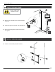
INSTRUCTION MANUAL 7 MOUNT THE WALL JAMB. NOTE CHOOSE 1 OF THE 2 HOLES AT THE TOP AND BOTTOM OF THE WALL JAMB. y 18 2 7A 7C 17 7B 18 7D 7A. Place the wall jamb (#2) on the threshold at distance "y" from the wall. Align it using a level. Trace the outer edge of the wall jamb and the holes on the wall. Remove the wall jamb. 7B. With a 1/4˝ drill bit, drill 3 holes into the wall using the marks as a guide. 7C. 7C(a) 7C(b) TOP VIEW TOP VIEW WALL STUD the drilled hole location, skip this step.
INSTRUCTION MANUAL 8 POSITION THE RETURN PANEL. REFER TO FOLLOWING PAGE 8A. Position the bottom glass clips (#11) as well as the threshold (#13) as shown. 8C 3a INTERIOR SHOWER SIDE 2 8A 8B. Slide the return panel (#3a) within the bottom glass clips as shown. 11 2 13 1”” 8C. Temporarily secure the return panel using a locking plier. 3/4”” 8B 8C. Temporarily secure the return panel using a locking plier. 8C 8D. Removal of the return panel is required prior to this.
INSTRUCTION MANUAL 8 POSITION THE RETURN PANEL.
INSTRUCTION MANUAL 9 POSITION THE FIXED PANEL. 9A. Align the magnetic gasket (#6) to the bottom 9A mallet. INTERIOR SHOWER SIDE 5 6 ALIGNMENT 9C CONT.
INSTRUCTION MANUAL 9 (CONT.) 4 5 DO NOT TIGHTEN COMPLETELY. 9D. Install the corner clips (#4) and the 9D. Position side panel (#5) in place within the bottom glass clips (#11). 9D 3 MITER SURFACES MUST BE FLUSH. 10 10A. 11 17 ADJUST THE GLASS PANELS. INTERIOR SHOWER SIDE (#5) to the door panel. 10B. Level all the glass panels by adjusting the hinges, corner clips and, if needed, insert clear setting blocks (#15&16) in the bottom glass clips.
INSTRUCTION MANUAL 11 FASTEN THE BOTTOM GLASS CLIPS. 11A. Realign the aluminum “u” channels on the threshold and drill a hole using a 1/8˝ drill bit at about 2˝ from the edge. Put a drop of silicone in each hole and fasten the “u” channels with a 3/4˝ long screw (#22). Cover each screw with the same clear setting block(s) (#17) used previously. 12 13 FASTEN THE RETURN PANEL. 12A 12A. Reposition et level the glass panels and the corner clips the same way as done in steps 8 to 10.
INSTRUCTION MANUAL 13 FASTEN THE SUPPORT BAR. THE ILLUSTRATIONS BELOW ARE GENERIC. YOUR MODEL DIFFERS FROM WHAT IS ILLUSTRATED YET THE INSTALLATION PROCEDURES REMAINS THE SAME. 5A 5A. 5B. 1 panel. The slotted screw head should be on the inside of the shower. shower as shown. Level it and trace the outline of the wall bracket on the wall. 5C 5B 5C. Isolate the wall bracket and drill a hole, using a 1/4” drill bit (ceramic drill bit if necessary) through the wall.
INSTRUCTION MANUAL 14 SILICONE SEAL THE SHOWER. HOURS 14A 7 INTERIOR SHOWER SIDE 13 14 14A. Silicone seal the exterior of the shower along the wall and the bottom glass clips (#11). 14B. Position the threshold (#13) under the door panel as illustrated. Lift it to pass a bead of silicone underneath. Apply silicone on the outside edges. 14B WE RECOMMEND TO HOLD THE THRESHOLD (#13) IN PLACE WITH TAPE WHILE DRYING.