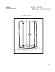
M-R94Z INSTRUCTION MANUAL Corner Round Shower door 08.
Please keep this manual and product code number for future reference and replacement parts ordering if necessary. GENERAL INSTRUCTIONS • Read this manual carefully and completely before proceeding. • It is recommended that you wear safety glasses at all times during the installation. INSTALLATION OVER CERAMIC TILES • Silicone should be used to seal the gap where the ceramic tiles meet the panel.
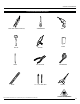
INSTALLATION MANUAL TOOLS AND MATERIAL REQUIRED LONG NOSE LOCKING PLIER (X2) SCREWDRIVERS SILICONE BLOCK CUTTING PLIER TAPE MEASURE MALLET PENCIL LEVEL DRILL 1/4˝& 1/8˝ DRILL BITS * To install the shower door on ceramic tiles, use a 1/4’’ drill bit for ceramic tiles SCISSOR 2 PEOPLE REQUIRED 3
INSTALLATION MANUAL INSTALLATION OF COMPONENTS FOLLOW INSTALLATION STEPS REQUIRED FOR THE MODEL STEP 7 STEP 1 • Wall Jambs Installation • Secure the expanders see page 6-8 see page 22 STEP 8 STEP 2 • Support bars installation • Fix panel assembly see page 23 see page 8-10 STEP 3 STEP 6 • Door panel assembly • Fix panel installation see page 10-11 see page 20-22 STEP 10 STEP 4 • Sealing • Cut the bottom gasket • Bottom gasket installation see page 26 see page 12-15 STEP 9 STEP 5 • Do
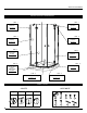
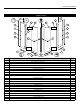
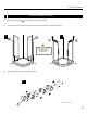
INSTALLATION MANUAL PARTS LISTING 1 1 11 8 10 10 2 8 2 13 HINGE 3 HINGE 3 11 4 4 5 5 12 12 HINGE HINGE 7 2 7 9 9 6 ITEM 1 PARTS SUPPORT BAR QTY 2 2 WALL JAMB (REGULAR PUNCH) 2 3 HINGED FIXED PANEL 2 4 EXPANDER 2 5 GASKET 2 6 ALUMINUM THRESHOLD 1 7 ALUMINIUM “U” CHANNEL 2 8 HINGE 4 9 BOTTOM DOOR GASKET 2 10 DOOR PANEL 2 11 SIDE PANEL GASKET 2 12 KNOB 13 MAGNETIC DOOR GASKET 2 2 ITEM PARTS QTY 14 SPACING BLOCKS 4 15 WALL PLUG 7 16 SCREW CAP
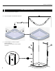
INSTALLATION MANUAL WALL JAMBS INSTALLATION 1 1a. Cut-out the template before installation. 1a 1b. Place the template on the threshold of the base. 1b 1c. Use the template to locate the wall jambs position on the base. Level and mark the position of the wall jambs on the wall.
INSTALLATION MANUAL 1 WALL JAMBS INSTALLATION (CONTINUED) 1d. Drill holes using Ø1/8’’ drill bit and use the wall jambs holes as reference. 1e. Remove the wall jambs. 1f. Insert one drop of silicone in each hole in the wall before inserting the wall plug. 1g. Before replacing the wall jambs on the base remove the template and add a drop of silicone on the bottom back of the wall jambs as illustrated.
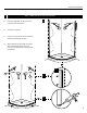
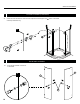
INSTALLATION MANUAL WALL JAMBS INSTALLATION (CONTINUED) 1 1h. Screw the two wall jambs into the wall plugs by using screws 1 1/4’’ (x6). Ensure verticality with the level. 1i. Place some silicone inside the bottom of the wall jamb. 1h 19 1i 2 2a. FIX PANEL ASSEMBLY Install the panel glass into the U channel temporarily. To have a correct place the U channel as shown. 3 RESPECT THE DIMENSION THAT IS INDICATED BELOW.
INSTALLATION MANUAL FIX PANEL ASSEMBLY(CONTINUED) 2 2b. Slide temporarily the two 2c. Level the glass panels and lock the position by clamping the wall jambs and expander with pliers. panel assemblies into the two wall jambs . 2b 2c 3 3 COVER THE PLIER’S TEETH BEFOREHAND TO AVOID SCRATCHING THE ALUMINUM PARTS. 2d. Unscrew the rear side of the 4 hinges as illustrated.
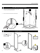
INSTALLATION MANUAL 2 2e. FIX PANEL ASSEMBLY(CONTINUED) Fasten the front side and one of the rear side component of the hinges to the Use the provided hex. Key. panels as illustrated. 2e 3 3a. DOOR PANEL ASSEMBLY Screw the two handles on the doors as illustrated.
INSTALLATION MANUAL 3 3b. DOOR PANEL ASSEMBLY (CONTINUED) Use a mallet to install the magnetic gaskets on the door panels. 13 3b THE MAGNETIC GASKETS AND THE DOOR PANNELS SHOULD BE ALIGNED ON THE TOP.
INSTALLATION MANUAL 4 CUT THE BOTTOM GASKET 4a. Cut the bottom gaskets with the following path using cutting pliers.
INSTALLATION MANUAL 4 CUT THE BOTTOM GASKET (CONTINUED ) 4b.
INSTALLATION MANUAL BOTTOM GASKET INSTALLATION 4 4c. (CONTINUED) Use a mallet to install the bottom gaskets on the door panels.
INSTALLATION MANUAL 4 4d. BOTTOM GASKET INSTALLATION (CONTINUED) Place the 4 spacing blocks under the bottom gaskets as illustrated.
INSTALLATION MANUAL 5 DOOR PANEL INSTALLATION 5a. Place the door centered on the base threshold. Level and align the holes of the doors and panels. 5a 2 PEOPLE REQUIRED INTERIOR SHOWER SIDE INTERIOR SHOWER SIDE LEVEL GLASS PANELS TO ALIGN THE HOLES.
INSTALLATION MANUAL 5 DOOR PANEL INSTALLATION (CONTINUED) 5b. Fasten the remaining rear side component of the hinges to the doors as illustrated. Use the provided hex. Key.
INSTALLATION MANUAL 5 5c. DOOR PANEL INSTALLATION (CONTINUED) Adjust the wall jambs and expanders so that the doors are closing properly. The magnetic gaskets must be aligned and in contact.
INSTALLATION MANUAL DOOR PANEL INSTALLATION (CONTINUED) 5 5d. Level and mark the position of the U channel on the base. 5d 5e. Remove the back side of the hinges the door and panels .
INSTALLATION MANUAL 6 FIX PANEL INSTALLATION 6a. Place the U channels on the position marks. 6b. Drill holes through the U channels using Ø1/8’’ drill bit . 6a 6b 7 7 1” ”1 6c. Remove the two U channels. 6d. Insert one drop of silicone in each hole in the base before replacing the aluminum “U” channels. 6e. Screw the two aluminum 6c into the base by using screws 1 1/4’’ (x2).
INSTALLATION MANUAL 6 FIX PANEL INSTALLATION (CONTINUED) 6f. Place the clear setting blocks 1 over the screws . 6g. panels into the wall jambs and the aluminium “U” channels and clamp the expanders to the wall jambs. Insert the two Level the glass panels and if necessary use also the clear setting blocks 2 (#22) . 6f 6g 21 6h Use a mallet to install the side gasket on the two panels. Place the lip side towards the inside of the shower.
INSTALLATION MANUAL 6 FIX PANEL INSTALLATION (CONTINUED) 6k 6i. Replace the doors on the base threshold. 6j. Reinstall the back side of the hinges. 6k. Remove the spacing blocks and make sure that magnetic gaskets are still aligned and in contact. INSTALLATION DE LA BARRES 6i 6j 7 SECURE THE EXPANDERS 7a. Secure the panels with the screws 3/8” (x6) ensuring that the magnetic gaskets are still in contact . Place the caps on the heads of apparent screws. 7b.
INSTALLATION MANUAL 8 SUPPORT BARS INSTALLATION 8a 8a. Loosen Align theBARS slotte to the DE SUPPORT / the glass clip. SUPPORT INSTALLATION panel. The slotted screw head should be on the inside of the shower. 1 8b. Rest the support bar on the panel inside the tub. Level it and trace an arc on the wall. 8b 8c. Isolate the wall bracket and drill a hole, using a 1/4˝ drill bit through the wall. Locate the position of this hole by way of the wall bracket. Insert a wall plug. 8d.
INSTALLATION MANUAL 9 ACCESSORIES INSTALLATION 9a Place temporarily the aluminum threshold at a distance of 1/8” from the two “U” channels towards the outside of the shower. INTERIOR SHOWER SIDE 9 Top view 7 9b Mark on the base the position of the threshold .
INSTALLATION MANUAL 9 ACCESSORIES INSTALLATION (CONTINUED) 9c Apply a bead of silicone to the underside of the threshold. 9d Replace the threshold on the base on the line marked previously .
INSTALLATION MANUAL 10 SEALING 10a Silicone the outside of the shower, around the wall jamb, below of the and around the U channels. panels and the exterior side of the aluminium threshold 10b Wait 24 hours before using the shower to dry the silicon.