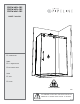
PDR2W-4836-CRP PDR2W-6036-CRP PDR2W-6042-CRP OWNER’S MANUAL Custom Order FINISH 11- Bright Chrome 35- Stainless Steel GLASS Clear 12 mm 2 PEOPLE REQUIRED P003 IT IS MANDATORY TO HAVE A WALL STUD ON EACH SIDE OF THE SHOWER UNIT TO SECURELY FASTEN THE RAIL TO THE WALLS. 06.
TABLE OF CONTENTS FIXE / FIXED PANEL 1 PANNEAU PARTS LISTING ........................................................ 3 PARTS TABLE .......................................................... 4 PROVIDED HARDWARE ............................................... 5 REQUIRED TOOLS AND MATERIALS ................................. 5 WALL JAMB INSTALLATION .......................................... 6 DOOR PANEL. ......................................................... 7 RETURN PANEL..................................
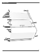
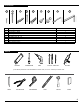
16A 15 16C 16B 10 14 4 1 8 12 17 9 13 2 11 18 5 4 3 5 6 7 12 PARTS LISTING 3
16b 16c 17 18 16a 15 1 2 3 4 5 6 7 8 9 10 11 12 13 14 Threshold (return panel) Door panel side gasket Fixed panel gasket Door bottom gasket Return panel glass mount bracket Universal expander Wall jamb (Flat) Return panel Gasket Door panel Fixed panel Bottom center guide Straight handle Running rail Set of double rollers Wall bracket for running rail Door stopper 1 1 1 1 1 1 1 2 sets 1 2 2 3 1 1 1 1 1 1 1 1 PARTS TABLE 4
HARDWARE 20 19 19 20 21 22 23 24 25 26 27 21 22 23 24 25 26 Self-drilling screw #6-1” Screw #12-3” Anchor (Blanc - White) Self drilling screw #8-1 1/4” Wall plug (Orange) Self drilling screw #8 - 3/8 screw cap Hex L key 3 mm Hex L key 6mm (7/32”) 27 4 2 3 3 4 3 4 1 1 TOOLS * HACKSAW SCREWDRIVERS DRILL 1/4˝&�1/8˝ DRILL BITS SILICONE If the shower panels are to be assembled on ceramic tiles, use a 1/4˝ drill bit for ceramic tiles.
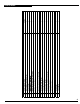
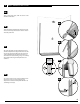
1 WALL JAMB INSTALLATION 1A Using a measuring tape, mark the center of the threshold of the base. 1A 1B Using the marking established in the previous step, run a second line up the wall. Use a level to ensure verticality of this line. B 1B 1C Place the wall jamb onto the wall while ensuring that the wall jamb holes align themselves onto the line running up the wall. Moreover, the side holes of the wall jamb (16a) should face the interior of the shower.
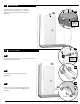
2 DOOR PANEL Using the cardboard packaging box as platform, install bottom door gasket (13) onto door panel (17) using a block and a mallet. Notice the gasket orientation. 17 2A 17 13 INTERIOR SHOWER SIDE 16b 3 RETURN PANEL 3A 14 3A I n s t a ll t h e r e t u r n p a n e l g la s s m o u n t b r a c k e t ( 1 4 ) t o the return panel (16b) as shown. INTERIOR SHOWER SIDE 15 6 3B 3B Insert gaskets into the glass clips for bottom xed panel (6).
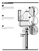
3 CONTINUED 3D 3D Slide the return panel assembly (15) (16b.c) into the wall jamb (16a) so as to allow the return panel (16b), along with the clips for bottom of xed panel (6), to rest on the threshold of the base. 16a 15 16b 16a 3E 3E 15 Mark the glass clips for bottom of xed panel (6) locations on the base, ensuring that the leading edge of the return panel is tangent to the center of threshold of the base.
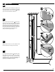
4 CONTINUED 3H 3H Ensure that the return panel (16b) is vertical by way of a level. If there need be a correction, adjust the verticality of the expander (15) in relation to the wall jamb (16a). 16b 3I 3I Once the return panel (16b) has been adjusted, secure the expander (15) to the wall jamb (16a) by way of a clamp so as to keep the return panel level. 16a 15 3J 3J By way of #8- 3/8 screws (24), as well as screw caps (25), permanently secure the wall jamb (16a) to the expander (15).
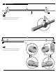
5 RUNNING RAIL 4 1 5A Position the stoppers (4) on the running rail (1) as illustrated. Secure them temporarily in place. 4 5B Position the wall brackets (2) on the running rail (1) as illustrated. Secure them temporarily in place.
FIXE / FIXED PANEL GLASS HOLDERS 6 1 PANNEAU 20 12 Fasten the running rail (1) to the fixed panel (18) with the glass holders (5). Secure them temporarily in place. INTERIOR SHOWER SIDE 5 Ensure that the running rail (1) is at the highest p o s s ib le p o s it io n in r e f e r e n c e t o t h e h o le s o f t h e fixed panel (18). 18 WASHER 5 1 Place the return panel onto a cushioned surface, such as a towel or cardboard so as to prevent unwanted damage.
8 FIXED PANEL 8A 1/2” max (12.7mm) Position the wide fixed panel assembly on threshold of the base (B) as shown. Adjust the wall bracket (3) as well as the return panel glass mount bracket (14) so as to ensure that the running rail (1) is secured. 3 18 18 12 The bottom guide (7) can hang off the threshold (B) as long as it can be well-fastened. 7 18 INTERIOR SHOWER SIDE B B 8B Ensure that the fixed panel gasket (12) collapses against the wall properly.
8 FIXED PANEL 8C 3 3 Mark the screw locations for the wall bracket (3) on the wall as well as the placement the glass clip (6) and bottom center guide (7). 6 7 7 6 6A 9 THRESHOLD S 9A Remove the fixed panel assembly (18) so as to allow placement of the threshold (9) onto the base. Ensure that a bead of silicone (S) is applied to the underside of the threshold before installing.
10 WIDE FIXED PANEL 3 21 10A Remove running rail (1) from brackets (3) (14). Drill holes in walls with a drill bit, intended for ceramic tiles, through to the wall stud. 1 1 14 3 OSSATURE WALL STUD Fasten the wall brackets (3) with #12-3 (20). 3 20 3 18 10A 6 7 Insert large fixed panel (18) back, ensuring that it’s placed in the bottom glass clip (6) and bottom center guide (7).
11 DOOR PANEL 11A Assemble a set of double rollers (2) to the door panel’s (1) top holes, as illustrated. 2 17 INTERIOR SHOWER SIDE 11B 17 Install door panel (17), ensuring that the rollers (2) are positioned over the running rail (1). Ensure that the door panel (17) is placed within the bottom center guide (7).
12 CONTINUED WASHER 12C 2 Install set of double rollers to the bottom holes of door panel (17), making sure that they are tangent to the running rail (1) by way of the excentric washers. 1 2 GLASS HOLE WASHER 13 STRAIGHT HANDLE Install straight handle (8) onto door panel (17). Ensure that clear washers on either side of glass are installed.
GASKET PANEL 14 DOOR PANEL SIDE / FIXED 14 Install door panel side gasket (11) onto door panel (17). 17 11 1/2” (12.
15 STOPPERS Adjust the position of the stoppers (4) so as to ensure a maximum opening and closing range for the door panel (17). 4 DOOR CLOSED Install fixed panel gasket (12) onto door edge after wiping it clean to ensure adhesion. 17 1 4 17 12 DOOR OPEN APPROX. 3” (76.2 mm) 17 16 SILICONE 8 18 Apply silicone (S) between the bottom of the fixed panel and the threshold of the base. Silicone application along the length of the threshold is also suggested.