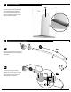
P-DRC1Y OWNER’S MANUAL SHOWER ENCLOSURES 2 PEOPLE REQUIRED 06.10 IT IS MANDATORY TO HAVE A WALL STUD ON EACH SIDE OF THE SHOWER UNIT TO SECURELY FASTEN THE RAIL TO THE WALLS.
TABLE OF CONTENTS FIXE / FIXED PANEL 1 PANNEAU CONFIGURATIONS AND PARTS LISTING ..................... 3,4,5,6 PROVIDED HARDWARE ............................................... 7 REQUIRED TOOLS AND MATERIALS ................................. 7 DOOR PANEL PLACEMENT ........................................... 8 COMPONENTS INSTALLATION. ...................................... 8 FIXED PANEL AND RETENTION GASKET ............................ 9 FIXED PANEL PLACEMENT ..................................
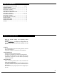
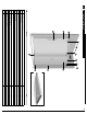
1a LL 4 2 1 3 RUNNING RAIL Ø1.00" (25.
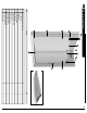
9 3 1 5 2 1 2 6 RUNNING RAIL Ø1.00" (25.
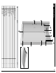
1c RL 2 5 9 1 3 4 7 2 1 BILL OF MATERIALS 6 RUNNING RAIL Ø1.00" (25.
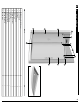
1d RR 4 3 1 9 5 6 1 8 2 BILL OF MATERIALS 2 7 1 0 1 1 ABSL66-18R RUNNING RAIL Ø1.00" (25.
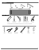
HARDWARE 19 18 21 20 ITEM QTY HARDWARE 18 #10-2 1/2 SCREW 4 19 #6-1 SCREW 2 20 HEX KEY 3mm 1 21 HEX KEY 6mm (7/32˝) 1 OUTILS / TOOLS * HACKSAW SCREWDRIVERS DRILL 1/4˝& 1/8˝ DRILL BITS SILICONE If the shower panels are to be assembled on ceramic tiles, use a 1/4˝ drill bit for ceramic tiles.
1 LR BEGIN THE INSTALLATION PROCEDURE AT PAGE 9. LL BEGIN THE INSTALLATION PROCEDURE AT PAGE 18. RL BEGIN THE INSTALLATION PREOCEDURE AT PAGE 9. CONSIDER THAT THE ILLUSTRATIONS ARE RELEVANT TO MODEL LR. AS SUCH MIRRORING THE ILLUSTRATIONS IS NECESSARY FOR THIS UNIT. RR BEGIN THE INSTALLATION PROCEDURE AT PAGE 18. CONSIDER THAT THE ILLUSTRATIONS ARE RELEVANT TO MODEL RR. AS SUCH MIRRORING THE ILLUSTRATIONS IS NECESSARY FOR THIS UNIT.
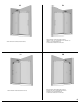
1 DOOR PLACEMENT 7 Place door panel (7) within the showering area to simplify following installation procedures. Ensure placing the panel onto a cushioned surface, such as a towel or cardboard, to prevent damage either to the panel or the base. 2 COMPONENTS INSTALLATION 2 3 2A 2A Position the glass fasteners (4), stoppers (3) and wall brackets (2) on the running rail (1) as illustrated. 4 1 2 2B Temporarily secure the mentioned components.
3 FIXED PANEL AND RETENTION GASKET Fasten the running rail (1) to the fixed panel (7) with the glass holders (4). Secure them temporarily in place. Thoroughly clean the edge of the fixed panel (7) with a cloth and degreasing solution. Split the door gasket (10) in two and apply the larger half of the gasket on the edge of the fixed panel on the wall side, after having removed the protective film (P).
1 4 FIXED PANEL PLACEMENT 4A Begin by removing the bottom glass clip’s and bottom guide’s fixed panel retainers (11) (12) from their assembly. 11 4A 12 4B Position the bottom glass clip (11) and bottom guide (12) on fixed panel (7) as illustrated. 4B 11 4C 12 Ensure that the running rail (1) is at the highest possible position in reference to the holes of the fixed panel (7). Adjust the fixed panel (7), by way of the running rail (1), so as to force the gasket (10) against the wall.
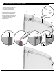
5 CONTINUED 5A 7 Remove the fixed panel assembly (7) and carefully lean it to the side, ensure that it is placed on a protective surface. Moreover, ensure that the wall bracket supports (2) are removed to proceed. 2 5A 5B Drill holes in walls with a drill bit, intended for ceramic tiles, through to the wall stud. 5C 5B WALL STUD Fasten the wall brackets (2) with included screws.
6 CONTINUED 8A 8B Reposition the fixed panel assembly in place, ensuring that the fixed panel (7) nests within the bottom glass clip retainers (11) (12) and that the wall bracket blocks (2) insert themselves within their back plates. Permanently secure the wall brackets by way of the socket cap screws, as illustrated. 2 11 12 7 7 TOP ROLLERS INSTALLATION Assemble a set of double rollers (5) to the door panel’s (6) top holes. Note the position of the excentric washers in the illustrations.
8 DOOR PANEL PLACEMENT PARALLEL Install door panel (6), ensuring that the rollers (5) are positioned over the running rail (1). Through the use of the nonconcentric washers, adjust rollers so that the sliding door panel (6) is as parallel to the wall as possible. 8A 5 Ensure that the door panel (6) is placed within the bottom center guide (12). If the bottom of the door panel and the guide create rubbing, adjust the excentric rollers to Position 1 of Step 7.
10 STRAIGHT HANDLE Install straight handle (8) onto sliding door (6). Ensure that clear washers on either side of glass are installed. 8 6 11 GASKETS INSTALLATION 11A Install the door mid-gasket (9) to the door panel (6) by way of a protective block and mallet. Start from the bottom edge of the door panel and work the gasket up. Ensure that a 1/2’’ gap remains between the running rail (1) and the top edge of the mid-gasket (9) for clearance.
12 STOPPERS ADJUSTMENT Adjust the position of the stoppers (3) so as to ensure a maximum opening and closing range. Ensure that the sliding door gasket (10) is forced against the wall when the door is closed.
13 THRESHOLD INSTALLATION Cut the threshold (13) to the necessary opening ensuring optimal water retention. Proceed to applying a bead of silicone to the underside of the threshold and placing it on the threshold of the base. 13 13 13 CUT TO OPENING WITH HACKSAW 14 SILICONE Apply silicone (S) between the bottom of the fixed panel and the threshold of the base. This is done from the outside of the shower area.
1 DOOR PLACEMENT 6 Place door panel (6) inside tub to simplify following installation procedures. Ensure placing the panel onto a cushioned surface, such as a towel or cardboard, to prevent damage either to the panel or the tub. 2 COMPONENTS INSTALLATION 3 2A 2 Fasten the running rail (1) to the fixed panel (7) with the glass holders (4). Secure them temporarily in place. 4 1 3 2B Fasten the running rail (1) to the fixed panel (7) with the glass holders (4). Secure them temporarily in place.
3 FIXED PANEL AND RETENTION GASKET Fasten the running rail (1) to the fixed panel (7) with the glass holders (4). Secure them temporarily in place. FOR FIXED PANEL Thoroughly clean the edge of the fixed panel (7) with a cloth and degreasing solution. Split the door gasket (10) in two and apply the one half of the gasket on the edge of the fixed panel on the wall side, after having removed the protective film (P).
4 FIXED PANEL PLACEMENT 4A Begin by removing the bottom glass clip’s and bottom guide’s fixed panel retainers (11) (12) from their assembly. 4A 11 12 4B Position the bottom glass clip (11) and bottom guide (12) on fixed panel (7) as 4B 4C Ensure that the running rail (1) is at the highest possible position in reference to the holes of the fixed panel (7). Adjust the fixed panel (7), by way of the running rail (1), so as to force the gasket (10) against the wall.
5 CONTINUED 5A 7 Remove the fixed panel assembly (7) and carefully lean it to the side, ensure that it is placed on a protective surface. Moreover, ensure that the wall bracket supports (2) are removed to proceed. 5A 2 5B Drill holes in walls with a drill bit, intended for ceramic tiles, through to the wall stud. 5C Fasten the wall brackets (2) with included screws.
6 CONTINUED Reposition the fixed panel assembly in place, ensuring that the fixed panel (7) nests within the bottom glass clip retainers (11) (12) and that the wall bracket blocks (2) insert themselves within their back plates. Permanently secure the wall brackets by way of the socket cap screws, as illustrated. 2 11 7 12 7 TOP ROLLERS INSTALLATION Assemble a set of double rollers (5) to the door panel’s (6) top holes. Note the position of the excentric washers in the illustrations.
8 DOOR PLACEMENT PARALLEL Install door panel (6), ensuring that the rollers (5) are positioned over the running rail (1). Through the use of the nonconcentric washers, adjust rollers so that the sliding door panel (6) is as parallel to the wall as possible. 5 Ensure that the door panel (6) is placed within the bottom center guide (12). If the bottom of the door panel and the guide create rubbing, adjust the excentric rollers to Position 1 of Step 7.
10 HANDLE INSTALLATION Fasten the running rail (1) to the fixed panel (7) with the glass holders (4). Secure them temporarily in place. 8 6 11 GASKETS INSTALLATION 11A Install the door mid-gasket (9) to the door panel (6) by way of a protective block and mallet. Start from the bottom edge of the door panel and work the gasket up. Ensure that a 1/2’’ gap remains between the running rail (1) and the top edge of the mid-gasket (9) for clearance.
12 STOPPERS ADJUSTMENT Adjust the position of the stoppers (3) so as to ensure a maximum opening and closing range. Ensure that the sliding door gasket (10) is forced against the wall when the door is closed.
13 THRESHOLD INSTALLATION Cut the threshold (13) to the necessary opening ensuring optimal water retention. Proceed to applying a bead of silicone to the underside of the threshold and placing it on the threshold of the base. 13 13 COUPER SELON L’OUVERTURE AVEC UNE SCIE À MAIN 13 14 SILICONE Apply silicone (S) between the bottom of the xed panel and the threshold of the base. This is done from the outside of the shower area.