SA1530z REPAIR MANUAL
These instructions are intended to help restore any ailing SA1530z Active Loudspeaker back to factory working conditions. They show how to remove and replace the drivers and the amplifier assembly. Please contact Mackie Tech Support (1-800-898-3211) to receive a Service Request Number and Order Number for parts needed for this restoration. They will also help you determine the nature of the problem and what parts will repair the unit.
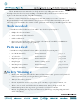
Led PCB replacement: 1 5 2 6 3 7 4 8 1 2 3 4 Carefully remove the cable attached to the led PCB assembly. 5 Use the phillips head screwdriver to remove one screw near the center of the led PCB assembly. 6 Carefully remove the led PCB assembly from the back side of the grill. 7 The hard part is done, the rest is easy! Place the new led PCB assembly (part #0007334) where the old one was. Follow the same steps as above, but backwards 6 to 1.
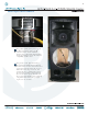
Woofer replacement: 1 Follow steps 1-4 of the led PCB replacement instructions, as the grill will need to be removed in order to access the woofer. 1 2 Keep the eight screws and flat washers in a safe place. 4 Carefully begin to remove the woofer. This woofer has a tendency to want to pop out, so please be sure to hold the woofer in place with your free hand while removing the screws with the other hand. Caution: The woofer is approximately 21 pounds.
Woofer replacement continued: Push down + 5 The positive (solid yellow) and negative (yellow and black) cables are still attached to the woofer terminals. Remove the cables from their terminals simply by pushing down on the terminal and pulling out the cable. 6 The picture on the right shows what the SA1530z looks like with the grill and woofer removed . Place the new woofer (part #0011777) where the old one was.
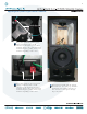
High Frequency Driver replacement: 1 Follow steps 1-4 of the led PCB replacement instructions, as the grill will need to be removed in order to access the high frequency driver. 1 2 3 14 4 13 5 12 6 11 10 9 8 3 Keep the fourteen screws and flat washers in a safe place. High Frequency Driver 7 Mid Frequency Driver 4 2 Fourteen screws and flat washers need to be removed from the horn assembly using the phillips head screwdriver.
High Frequency Driver replacement continued: + Push down The positive (solid blue) and negative (blue and black) cables are still attached to the high frequency driver terminals. Remove the cables from their terminals simply by pushing down on the terminal and pulling out the cable. + 5 - Push down 6 The positive (solid green) and negative (green and black) cables are still attached to the mid frequency driver terminals.
High Frequency Driver replacement continued: +2 1 4 3 9 1 2 + - 4 8 Keep the four screws and locking washers in a safe place. 10 3 Four screws and locking washers may be removed from the high frequency driver using the phillips head screwdriver. Notice the placement of the terminals, as well. The high frequency driver should easily lift right off of the horn assembly. Holding down the horn assembly with one hand while lifting up on the driver with the other hand may help.
High Frequency Driver replacement continued: 1 2 4 3 11 Turning the high frequency driver over reveals the cover plate which needs to be removed using the phillips head screwdriver. Keep the four screws in a safe place. Replace with the new driver (part #0013925) and follow the same steps as above, but backwards 11 to 1. Power up the SA1530z and the new driver should now be pumping out those highs again.
Diaphragm replacement: 1 At the present time (January 2007), diaphragms are not currently available, so you will have to replace the complete driver following the previous section (pages 6-9). If you have received a diaphragm, please follow the steps below. 2 Follow steps 1-6 of the high frequency driver replacement instructions, as the horn assembly will need to be removed in order to access the diaphragm. 4 5 The diaphragm and plate adapter are easily removed from the horn assembly.
Mid Frequency Driver replacement: 1 Follow steps 1-6 of the high frequency driver replacement instructions, as the grill and horn assembly will need to be removed in order to access the mid frequency driver. 3 Keep the eight screws and locking washers in a safe place. 2 1 Pull out 8 3 7 4 - + 2 - 1 5 3 8 + +- 6 Pull out 6 2 +- 7 4 5 Eight screws and locking washers may be removed from the mid frequency driver cover plate using the phillips head screwdriver.
Mid Frequency Driver replacement continued: 1 +- 4 2 1 - 5 6 Keep the four screws and locking washers in a safe place. 7 The mid frequency driver easily lifts right off of the horn. Replace with the new driver (part #0013897) and follow the same steps as above, but backwards 7 to 1. Power up the SA1530z and the new driver should now be pumping out those mids again.
Amplifier Assembly replacement: 1 2 18 3 17 4 16 5 15 6 14 7 13 8 12 9 11 1 10 Eighteen screws need to be removed from the amplifier assembly using the phillips head screwdriver. The amplifier assembly is capped by two cover plates outlined above. 2 Keep the eighteen screws in a safe place. 3 The covers may be worked loose by wedging a flat head screwdriver in between the cabinet and the cover, as well as the amplifier assembly and cover.
Amplifier assembly replacement continued: 1 1 2 3 4 5 6 7 5 2 4 Once the two cover plates are removed, two more screws need to be taken out in order to separate the amplifier assembly from the cabinet. Keep the two screws in a safe place. The amplifier assembly is now ready to be separated from the cabinet.
Amplifier assembly replacement continued: 1 Edge of amplifier assembly 2 3 1 Edge of amplifier assembly 6 Closeups of the led PCB cable and connector are shown above. The black wire of the cable is closest to the ribbon cable. The cable only fits in one way. 7 4 5 6 7 2 3 4 5 6 7 Now for the closeups of the driver terminals. Make sure the cables are reconnected to the same terminals they were removed from (but on the new amplifier assembly).
Amplifier assembly replacement continued: 8 Place the new amplifier assembly (part #0013839-00) where the old one was. Follow the same steps as above, but backwards 7 to 1. Remove the serial number from the faulty amplifier assembly (as shown in picture above) and place on the new amplifier assembly. Power up the SA1530z and relish in the fact that you just replaced an amplifier assembly.
This page left blank intentionally