BreezeMAX™ TDD Modular Base Station System Manual SW Version 4.
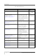
Document History Document History Topic Description Version/Date Issued First Release New Product Manual SW Version 4.0.1, October 2006 Output power range of Control range of new 2.x GHz SW Version 4.0.2 2.x GHz AU-ODUs. Section 1.5.1, AU-ODU units (HC08 version December 2006 Section 2.1, Section 4.8.4.4 137) is 30 - 36 dBm. If diversity is used, all ODUs connected to the same AU-IDU must use the same HC08 version. Available AU-ODU units Added SW Version 4.0.2 Section 1.5.1, Section 1.5.
Document History Topic Description Version/Date Issued Best BST/AU Parameters Updated explanations. Added SW Version 4.0.2 Section 4.10.7.3.10 Best BST/AU ID and Best December 2006 BST/AU ID Mask (replace Base Station ID and Base Station ID Mask in the SU MAC menu that starting from this version will not be applicable for units operating in TDD/Advanced Si mode). Radio Parameters Updated explanations. Added SW Version 4.0.2 Section 4.10.7.3.
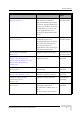
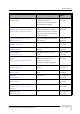
Document History Topic Description Version/Date Issued 3.3 GHz band New frequency band SW Version 4.1 Section 1.1, Section 1.5.1, April 2007 Section 4.8.5 IP address configuration Updated limitations SW Version 4.1 April 2007 Section 4.3, Section 4.5.4.2.2.1, Section 4.5.4.3.2.1, Section 4.6.3.1.1, Section 4.6.3.1.3, Section 4.6.3.2.1, Section 4.6.3.2.3, Section 4.6.3.3.3.1 Switching Mode New feature (IP CS Switching SW Version 4.1 Section 1.1, Section 4.5.2.
Document History Topic Description Version/Date Issued ODU - Show (for a selected ODU) Updated (Tx Power changed to SW Version 4.1 Section 4.8.2.1 Configured Tx Power, April 2007 Associated to AU:Channel and Actual Tx Power added) ARQ ARQ Enable/Disable and SW Version 4.1 Section 4.9.5.1, Section 4.9.5.3.1, counters applicable for ARQ April 2007 Section 4.9.5.3.4, Section 4.9.6.
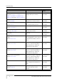
Document History Topic Description Version/Date Issued CT in BE QoS CT in BE QoS is not SW Version 4.1 Sections 4.11.4.7, 4.11.4.7.3, configurable (set to Short) July 2007 Ber Test BER Test feature is not SW Version 4.1 Section 4.9.6.2 supported in current version July 2007 RADIUS description Added detailed description of SW Version 4.1 Section 4.5.
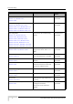
Document History Topic Description Version/Date Issued Forwarding Rules functionality Updated description SW Version 4.1 Section 4.11.1.1 L2, PPPoE and VoIP Services July 2007 Updated descriptions functionality SW Version 4.1 July 2007 Section 4.11.1.2 NPU Parameters Summary Section 4.12 BreezeMAX Modular Base Station System Manual Updated to reflect all changes SW Version 4.
Legal Rights Legal Rights © Copyright 2007 Alvarion Ltd. All rights reserved. The material contained herein is proprietary, privileged, and confidential and owned by Alvarion or its third party licensors. No disclosure thereof shall be made to third parties without the express written permission of Alvarion Ltd. Alvarion Ltd. reserves the right to alter the equipment specifications and descriptions in this publication without prior notice.
Legal Rights invoice date (the "Warranty Period")". During the Warranty Period, Alvarion may release to its Customers firmware updates, which include additional performance improvements and/or bug fixes, upon availability (the "Warranty"). Bug fixes, temporary patches and/or workarounds may be supplied as Firmware updates. Additional hardware, if required, to install or use Firmware updates must be purchased by the Customer.
Legal Rights WARRANTIES OR CONDITIONS, EXPRESS OR IMPLIED, EITHER IN FACT OR BY OPERATION OF LAW, STATUTORY OR OTHERWISE, INCLUDING BUT NOT LIMITED TO WARRANTIES, TERMS OR CONDITIONS OF MERCHANTABILITY, FITNESS FOR A PARTICULAR PURPOSE, SATISFACTORY QUALITY, CORRESPONDENCE WITH DESCRIPTION, NON-INFRINGEMENT, AND ACCURACY OF INFORMATION GENERATED. ALL OF WHICH ARE EXPRESSLY DISCLAIMED. ALVARION' WARRANTIES HEREIN RUN ONLY TO PURCHASER, AND ARE NOT EXTENDED TO ANY THIRD PARTIES.
Legal Rights and industrial environments. This equipment generates, uses, and can radiate radio frequency energy and, if not installed and used in accordance with the instruction manual, may cause harmful interference to radio communications. Operation of this equipment in a residential area is likely to cause harmful interference in which case the user will be required to correct the interference at the user's own expense.
Legal Rights Safety Considerations - DC Powered Equipment (BST & Power Feeder) CAUTION ATTENTION Risk of electric shock and energy hazard.Disconnecting one Power Interface Unit (PIU) disconnects only one PIU module. To isolate the Base Station completely, disconnect both PIUs Risque de décharge électrique et d'electrocution. La déconnection d'un seul module d'alimentation (PIU) n'isole pas complètement la Station de Base.
Legal Rights Caution To avoid electrical shock, do not perform any servicing unless you are qualified to do so. Line Voltage Before connecting this instrument to the power line, make sure that the voltage of the power source matches the requirements of the instrument. Radio The instrument transmits radio energy during normal operation. To avoid possible harmful exposure to this energy, do not stand or work for extended periods of time in front of its antenna.
Legal Rights Important Notice This user manual is delivered subject to the following conditions and restrictions: This manual contains proprietary information belonging to Alvarion Ltd. Such information is supplied solely for the purpose of assisting properly authorized users of the respective Alvarion products.
Legal Rights damage and/or bodily harm and/or void the user's authority to operate the equipment and/or revoke the warranty provided by such manufacturer.
About This Manual This manual describes the BreezeMAX TDD ("BreezeMAX") Base Station equipment, and details how to install, operate and manage the system components. This manual is intended for technicians responsible for installing, setting and operating the BreezeMAX Base Station equipment, and for system administrators responsible for managing the system. This manual contains the following chapters and appendices: Chapter 1 - System description: Describes the BreezeMAX system and its components.
Contents Chapter 1 - System Description 1.1 Introducing BreezeMAX................................................................................................ 2 1.2 Base Station Equipment ............................................................................................... 6 1.2.1 Base Station Chassis ........................................................................................... 6 1.2.2 Network Processing Unit (NPU)...................................................................
Contents 1.5.4 AU-IDU to AU-ODU Communication.................................................................. 22 1.5.5 Data Communication (Ethernet Ports) ............................................................... 22 1.5.6 Configuration and Management......................................................................... 23 1.5.7 Environmental .................................................................................................... 23 1.5.8 Standards Compliance, General ................
Contents 2.2.11 Air Ventilation Unit (AVU)................................................................................... 59 2.2.12 Replacing Base Station Components ................................................................ 59 2.3 Installing the ODU Power Feeder............................................................................... 63 2.3.1 Installation Requirements................................................................................... 63 2.3.2 The ODU Power Feeder ..........
Contents 3.2.5 Verifying the Ethernet Connection ..................................................................... 85 Chapter 4 - Operation and Administration 4.1 BreezeMAX System Management.............................................................................. 88 4.2 The Monitor Program .................................................................................................. 90 4.2.1 Accessing the Monitor Program ........................................................................
Contents 4.6.4 Performance Monitoring................................................................................... 139 4.7 Radio Cluster Menu................................................................................................... 143 4.7.1 Show Summary................................................................................................ 143 4.7.2 Select ............................................................................................................... 144 4.7.3 Add...
Contents 4.10.7 SU # Menu ....................................................................................................... 177 4.10.8 Add New SU..................................................................................................... 198 4.10.9 Clear All Configured SU SW Files.................................................................... 198 4.11Services Menu........................................................................................................... 199 4.11.
Contents B.3.2 Voice RTP BW Calculation .............................................................................. 270 B.3.3 Voice RTCP BW Calculation............................................................................ 270 B.3.4 T.38 14,400 Kbps Fax RTP BW Calculation .................................................... 270 B.3.5 FAX RTCP BW Calculation.............................................................................. 271 B.3.6 QoS Profiles ..........................................
Figures Figure 1-1: BreezeMAX System Architecture................................................................................ 5 Figure 2-1: AU-ODU-HP Pole Installation Using Special Clamps ............................................... 36 Figure 2-2: AU-ODU-HP Pole Installation Using Metal Band...................................................... 37 Figure 2-3: Bottom Panel of the AU-ODU (except 2.3 GHz WCS).............................................. 38 Figure 2-4: Bottom Panel of the AU-ODU - 2.
Tables Table 1-1: Number of AU-IDUs, AU-ODUs and Power Feeders Required for Various Configurations with regular PIU(s) .............................................................................................................. 11 Table 1-2: Number of AU-IDUs, AU-ODUs and Power Feeders Required for Various Configurations with High-Power PIU(s) ......................................................................................................
Tables Table 2-6: PIU LEDs ................................................................................................................... 47 Table 2-7: PSU Requirements, Configurations with one NPU (excluding PSU redundancy) ..... 49 Table 2-8: PSU LEDs .................................................................................................................. 50 Table 2-9: AU-IDU LEDs .............................................................................................................
Tables Table 4-5: Automatic Association of Channel 1 Upon First Power-Up...................................... 164 Table 4-6: Rates (Modulation Schemes and Coding) ............................................................... 168 Table 4-7: Scanning Intermediate Steps ................................................................................... 194 Table 4-8: Hybrid VLAN Mode ..................................................................................................
1 Chapter 1 - System Description In This Chapter: “Introducing BreezeMAX” on page 2 “Base Station Equipment” on page 6 “Networking Equipment” on page 14 “Management Systems” on page 15 “Specifications” on page 18
Chapter 1 - System Description 1.1 Introducing BreezeMAX BreezeMAX TDD (BreezeMAX) is Alvarion's WiMAX compatible platform operating in Time Division Duplex (TDD) mode. It leverages Alvarion's market-leading knowledge of Broadband Wireless Access (BWA), industry leadership, proven field experience, and core technologies including many years of experience with OFDM technology. Built from the ground up based on the IEEE 802.
Introducing BreezeMAX 4-channel Access Unit and high-power radios at the Base Station 2nd or 4th order transmit diversity at the Base Station. 4th order receive diversity at the Base Station using Maximum Receive Ratio Combining (MRRC). Uplink sub-channels using OFDMA-16 for increased service efficiency and improved link budget. A high-power CPE with an integral antenna array, providing 360 degrees coverage with smart selection of Tx and Rx antennas.
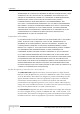
Chapter 1 - System Description Base Station (BST) Equipment: BreezeMAX Base Station equipment, including the modular Base Station, Outdoor Radio Units, GPS Receiver and other components. Networking Equipment: Standard switches/routers and other networking equipment, supporting connections to the backbone and/or Internet. Management Systems: SNMP-based Management, RADIUS server(s) and other Operation Support Systems.
Introducing BreezeMAX Figure 1-1: BreezeMAX System Architecture BreezeMAX Modular Base Station System Manual 5
Chapter 1 - System Description 1.2 Base Station Equipment The Multi Carrier, High Power, Full Duplex Base Station provides all the functionality necessary to communicate with SUs and to connect to the backbone of the Service Provider. The Base Station comprises the following elements: 1.2.1 Base Station Chassis The Base Station equipment is based on an 8U high cPCI (compact Peripheral Component Interconnect) shelf designed for installation in a 19" or 21" (ETSI) rack.
Base Station Equipment Aggregate backbone Ethernet connectivity via a 100/1000 Base-T network interface. Traffic classification and connection establishment initiation. Policy based data switching. Service Level Agreements management. RADIUS NAS, enabling centralized SUs’ authentication and services authorization by RADIUS server(s). Centralized agent in the Base Station to manage all cell site's AUs and all registered SUs.
Chapter 1 - System Description Each AU-IDU includes four channels using a common PHY and MAC that can connect to up to four outdoor radio units, according to the selected diversity mode (refer to Section 1.2.5 below for more details). The AU-IDU module connects to the AU-ODUs via Intermediate Frequency (IF) cables carrying full duplex data, control and management signals between the AU-IDU and the AU-ODU, as well as power (-48 VDC) and 64 MHz synchronization reference clock from the AU-IDU to the AU-ODU.
Base Station Equipment The following figure describes the multi channel use to cover a cell of 360° with 4 sectors, using frequency reuse 1: The following figure describes the multi channel use to cover a cell of 360° with 4 sectors, using frequency reuse 1/2: 1.2.5.3 2nd Order Diversity Multiple channel configuration with second order diversity allows coverage of one sector with space diversity by a single AU-IDU and two ODUs connected to channels 1 and 2.
Chapter 1 - System Description 1.2.5.4 4th Order Diversity Multiple channel configuration with fourth order diversity allows a single sector coverage by a single AU-IDU with 4 ODUs. In each sector, both space and polarization diversities are implemented, using dual polarization slant antennas. The channels are paired: channels 1 and 2 form one pair, channels 3 and 4 form the second pair. The two ODUs connected to each pair are connected to the same dual polarization antenna.
Base Station Equipment Table 1-1: Number of AU-IDUs, AU-ODUs and Power Feeders Required for Various Configurations with regular PIU(s) Diversity Mode Number of Sectors (AU-IDUs) Number of ODUs Number of Power Feeders Second Order Diversity 3 6 - 4 8 - 6 12 1 3 12 1 4 16 2 6 24 4 Fourth Order Diversity Table 1-2: Number of AU-IDUs, AU-ODUs and Power Feeders Required for Various Configurations with High-Power PIU(s) Diversity Mode Number of Sectors (AU-IDUs) Number of ODUs Number o
Chapter 1 - System Description The regular PIU can support a total current of up to 35 A (@40.5 VDC), enabling support of a Base Station with up to 8 High-Power AU-ODUs (4 sectors using second order diversity). For configurations with a higher number of ODUs it is necessary to use Power Feeder(s). The High-Power PIU can support a total current of up to 58 A, enabling support of up to 20 High-Power AU-ODUs.
Base Station Equipment that all sectors will switch from transmit (downlink) to receive (uplink) at the same time. This synchronization is necessary to prevent Intra-site and Inter-site sectors interference and saturation (assuming that all sectors are operating with the same frame size and with the same DL/UL ratio). The GPS clock required is 1PPS with accuracy of 10-11 and maximum jitter of 100ns.
Chapter 1 - System Description 1.3 Networking Equipment The Base Station is connected to the backbone through standard data communication and telecommunication equipment. The NPU aggregates the traffic from all AUs, connecting to the backbone through a 100/1000 Base-T port. The point-to-point link from the Base Station to the backbone can be either wired or wireless. Alvarion offers the DUET 6004, a V5.2 to SIP Access Gateway connecting a Class 5 switch over V5.2 to its’ Voice Gateways. 1.3.
Management Systems provide telephony and advanced services over an IP network. It supports voice band data transmission of FAX G.3 (over G.711 or T.38), pay phone signaling (Tax and reverse polarity), CLI, as well as other services that are hook flash based (call waiting, hold, call forward, etc.). 1.4 Management Systems The end-to-end IP-based architecture of the system enables full management of all components, using standard management tools.
Chapter 1 - System Description Fault Management Configuration Management Service Management Data Collection Performance Monitoring Device embedded software upgrade Security Management Northbound interface to other Network Management Systems. Embedded with the entire knowledge base of BWA network operations, AlvariSTAR is a unique state-of-the-art power multiplier in the hands of the service provider that enables the provisioning of satisfied customers.
Management Systems On-line performance data monitoring Export of configuration details to a CSV file Support for Telnet cut-through to the Base Station and http cut-through to Gateways behind connected SUs. 1.4.3 BreezeMAX Service Manager BreezeMAX Service Manager provides centralized management of user authentication and authorization using the industry standard RADIUS protocol.
Chapter 1 - System Description 1.5 Specifications 1.5.1 Radio Table 1-4: Radio Specifications Item Description Frequency Unit/Band Frequency (MHz) AU-ODU-HP-2.3 2300 - 2360 AU-ODU-HP-2.3-WCS 2305 - 2317, 2348 - 2360 (incliudes WCS filter) AU-ODU-HP-2.5A 2496 - 2602 AU-ODU-HP-2.5B 2590 - 2690 AU-ODU-HP-TDD-3.3a 3300-3355 AU-ODU-HP-TDD-3.3b 3345-3400 AU-ODU-HP-TDD-3.4a 3399.5 - 3455 AU-ODU-HP-TDD-3.4b 3445 - 3500 AU-ODU-HP-TDD-3.5a 3500 - 3555 AU-ODU-HP-TDD-3.
Specifications Table 1-4: Radio Specifications Item Description Modulation OFDM in the Downlink, OFDMA-16 in the Uplink (N x SUs per Symbol, N=1-16), BPSK, QPSK, QAM16, QAM64 FEC Convolutional Coding: 1/2, 2/3, 3/4 Typical Sensitivity (BER=1E-6) Modulation & Coding Minimum SNR (dB) Sensitivity (dBm) @ 3.5 MHz BW Sensitivity (dBm) @ 5 MHz BW BPSK 1/2 2.5 -98.5 -97 QPSK 1/2 5.9 -94.5 -93 QPSK 3/4 8.6 -91.5 -90 QAM16 1/2 11.4 -87.5 -86 QAM16 3/4 14.8 -84.
Chapter 1 - System Description 1.5.2 Base Station 2.X GHz Antennas (Optional) Table 1-5: Base Station 2.X GHz Antennas, Electrical Specifications Item Description BS ANT 60/2.X V 16.5 dBi minimum in the 2.3-2.7 GHz band, 60°AZ x 7°EL sector antenna, vertical polarization, compliance with ETSI EN 302 326-3 V1.2.1 (2007-01) and RoHS BS ANT 90/2.X V 15.5 dBi minimum in the 2.3-2.7 GHz band, 90°AZ x 7°EL sector antenna, vertical polarization, compliance with ETSI EN 302 326-3 V1.2.
Specifications 1.5.3 Base Station 3.x GHz Antennas (Optional) Table 1-6: Base Station 3.x GHz Antennas, Electrical Specifications Item Description BS ANT 60V/3.3-3.8 16.5 dBi minimum in the 3.3-3.8 GHz band, 60° AZ x 7° EL, vertical polarization, compliant with ESTI EN 302 326-3 V1.2.1 (2007-01). BS ANT 90V/3.3-3.8 14.5 dBi typical in the 3.3-3.8 GHz band, 90° AZ x 9° EL, vertical polarization, compliant with ESTI EN 302 326-3 V1.2.1 (2007-01) BS ANT 120V/3.3-3.8 13 dBi typical in the 3.3-3.
Chapter 1 - System Description 1.5.4 AU-IDU to AU-ODU Communication Table 1-7: AU-IDU to AU-ODU Communication Item Description IF Frequency Tx: 240 MHz Rx: 140 MHz Ref Synchronization Frequency 64 MHz Bi-Directional Control Frequency 14 MHz IF cable Impedance 50 Ohm Maximum IF cable Attenuation 10 dB @ 240 MHz 7.
Specifications 1.5.6 Configuration and Management Table 1-9: Configuration and Management Item Description Out Of Band (OOB) Management Telnet via Management port SNMP via Management port Monitor port In Band (IB) Management via Data Port SNMP Telnet SNMP Agents SNMP ver 1 client MIB II (RFC 1213), Private BreezeMAX MIBs Authentication and Authorization RADIUS Software upgrade Using TFTP Configuration upload/download Using TFTP 1.5.
Chapter 1 - System Description 1.5.8 Standards Compliance, General Table 1-11: Standards Compliance, General Type Standard EMC ETSI EN 301 489-1/4 ETSI EN 300-385 EN 60950-1 Safety UL 60 950-1 Environmental ETS 300 019: Part 2-1 T 1.2 & part 2-2 T 2.3 for indoor & outdoor Part 2-3 T 3.2 for indoor Part 2-4 T 4.1E for outdoor ETSI EN 301 753 V.1.1.1 Radio ETSI EN 301 021 V.1.6.1 ETSI EN 302 326 FCC 04-135 FCC 27.53, FCC P.15, FCC P.
Specifications 1.5.
Chapter 1 - System Description 1.5.10 Physical and Electrical 1.5.10.1 Mechanical Specifications, Base station Equipment Table 1-13: Mechanical Specifications, Base Station Equipment Unit Dimensions (cm) Weight (kg) BST-SH 8U ETSI type shelf, 8U x 43.19 x 24 6.9 (excluding AVU) Regular PIU 3U x 5HP x 16 0.35 High-Power PIU 3U x 5HP x 16 0.45 PSU 3U x 8HP x 16 0.7 NPU 6U x 7HP x 16 0.7 AU-IDU-4CH 6U x 7HP x 16 0.6 AU-ODU-HP (except 2.3 GHz WCS models) 32.9 x 15.7 x 16.9.9 6.
Specifications 1.5.10.2 Electrical Specifications, Base station Equipment Table 1-14: Electrical Specifications, Base Station Equipment Unit Details Power Source -40.5 to -60 VDC Regular PIU Power Consumption: 16W maximum (active PIU) Maximum Supplied Current: 35 A High-Power PIU Power Consumption: 35W maximum (active PIU) Maximum Supplied Current: 58 A PSU 200W maximum output power Efficiency: 80% minimum NPU 65W maximum, 44W typical, excluding power that may be required for GPS Adapter (1.
Chapter 1 - System Description 1.5.10.3 Connectors, Base station Equipment Table 1-15: Connectors, Base Station Equipment Unit Connector Description Regular PIU -48V 3 pin/40A D-Type male. Amphenol P/N 717TWA3W3PHP2V4RRM6 (or equivalent) High-Power PIU -48V 5 pin/40A D-Type male. Harting P/N TB09693009044 (or equivalent) NPU DATA 100/1000Base-T (RJ-45) with 2 embedded LEDs. Cable connection to a PC: Crossed Cable connection to a hub: Straight MGMT 10/100Base-T (RJ-45) with 2 embedded LEDs.
Specifications Table 1-15: Connectors, Base Station Equipment Unit Connector Description Indoor GPS Receiver POWER 4 pins power plug TIME OF DAY CHANNEL 9-pin D-Type jack COMMAND CHANNEL 9-pin D-Type jack 2.048MHz BNC jack 1PPS BNC jack ANTENNA TNC jack Outdoor GPS Receiver 1.5.10.4 12-pin round plug Base Station 2.X GHz Antennas, Mechanical Specifications Table 1-16: Base Station 2.X GHz Antennas, Mechanical Specifications Unit Description Dimensions (cm) Weight (kg) BS ANT 60/2.
Chapter 1 - System Description 1.5.10.5 Base Station 3.x GHz Antennas, Mechanical Specifications Table 1-17: Base Station 3.x GHz Antennas, Mechanical Specifications Unit Description Dimensions (cm) Weight (kg) BS ANT 60V/3.3-3.8 Mounting kit: 2" to 4" pole 76.6 x 15 x 8.7 2.2 76.6 x 15 x 8.6 2.2 76.6 x 14.4 x 8.3 2.0 50 x 20 x 2.8 2 60 x 25 x 5.5 2 85.1 x 16 x 6.1 2 maximum 85.1 x 16 x 6.1 2 maximum 68.8 x 16 x 14.5 2 maximum 67.5 tubular, 8 diameter 0.
2 Chapter 2 - Installation Guidelines In This Chapter: “Installing the AU-ODU” on page 32 “Installing the Base Station Equipment” on page 41 “Installing the ODU Power Feeder” on page 63 “Installing the GPS Adapter” on page 67 NOTE Refer to the BreezeMAX Base Station Installation Manual for more detailed instructions on installation of the Base Station and its components.
Chapter 2 - Installation Guidelines 2.1 Installing the AU-ODU The following sections describe how to install the AU-ODU, including pole mounting the ODU and connecting the cables. For more detailed instructions, refer to the BreezeMAX TDD Base Station Installation & Maintenance Manual. NOTE In sectors with diversity (either second or fourth order diversity), new 2.
Installing the AU-ODU 2.1.2 Guidelines for Positioning the AU-ODU This section provides key guidelines for selecting the optimal installation locations for the AU-ODU and its antenna. CAUTION ONLY experienced installation professionals who are familiar with local building and safety codes and, wherever applicable, are licensed by the appropriate government regulatory authorities should install outdoor units and antennas.
Chapter 2 - Installation Guidelines maximum permitted DC resistance (the sum of the DC resistance of the inner and outer conductors) are provided in the following table. Table 2-1: IF Cables Requirements Item Description Screening Effectiveness 90 dB minimum in the 10-300 MHz band. IF cable Impedance 50 Ohm Maximum IF cable Attenuation 10 dB @ 240 MHz 7.5 dB @ 140 MHz 8 dB @ 64 MHz Maximum IF cable DC Resistance 1.
Installing the AU-ODU NOTE Install the unit with the bottom panel, which includes the LEDs, facing downward. 2.1.4.1 Pole Mounting the AU-ODU-HP Using Clamps Figure 2-1 illustrates the method of mounting a High Power AU-ODU-HP on a pole, using the clamps and threaded rods. Figure 2-1: AU-ODU-HP Pole Installation Using Special Clamps NOTE There is a groove on one end of the threaded rod.
Chapter 2 - Installation Guidelines 2.1.4.2 Pole Mounting the AU-ODU-HP Using Metal Bands Figure 2-2 illustrates the method of mounting a High Power AU-ODU-HP on a pole, using metal bands.
Installing the AU-ODU 2.1.5 AU-ODU Figure 2-3: Bottom Panel of the AU-ODU (except 2.3 GHz WCS) Figure 2-4: Bottom Panel of the AU-ODU - 2.
Chapter 2 - Installation Guidelines CAUTION Do not open the impermeability test screw - you may impair the sealing of the unit against moisture and humidity. Table 2-3: AU-ODU LEDs Name Description Functionality PWR Power indication Off - Power failure Green - Power to ODU is OK, internal 3.3 VDC power supply is OK. ALARM IDU-ODU communication and synthesizer status indication Off - IDU-ODU communication is OK, synthesizer is locked.
Installing the AU-ODU 2.1.6.2 Connecting the Antenna Cable To connect the RF cable: 1 Connect one end of the coaxial RF cable to the RF connector (marked ) located on the bottom panel of the unit. 2 Connect the other end of the RF cable to the antenna. 3 The RF connectors should be properly sealed to protect against rain and moisture. 2.1.6.3 Connecting the IF Cable To connect the IF cable: 1 Connect one end of the coaxial IF cable to the IF connector on the bottom panel of the unit.
Chapter 2 - Installation Guidelines 2.2 Installing the Base Station Equipment 2.2.1 BST Installation Requirements 2.2.1.1 Packing List Base Station Chassis: BMAX-BST-SH Base Station Chassis BMAX-BST-AVU Air Ventilation Unit (installed) Cables Tray kit BMAX-BST-PIU (1 or 2 per chassis) Power Interface Unit(s), or BMAX-4M-BST-PIU (1 or 2 per chassis) High-Power Interface Unit(s). A suitable DC power cable is supplied with each PIU.
Installing the Base Station Equipment Other installation tools and materials 2.2.2 BMAX-BST-SH Chassis Slot Assignments The Base Station chassis comprises 6 3U high slots and 9 6U high slots, as shown in Figure 2-5.
Chapter 2 - Installation Guidelines 2.2.3 Power Requirements Use the following table to calculate worst-case power source requirements for the Base Station equipment: Table 2-5: Power Requirements, Base Station Equipment Unit Details Power Source -40.
Installing the Base Station Equipment Example: A full 2.x GHz Base Station operating with DL-UL ratio of 60-40, with regular PIU(s), 6 AU-IDUs, 24 ODUs (8 ODUs are powered via the AU-IDUs, 16 ODUs are powered by 4 Power Feeders), a GPS Adapter and an Outdoor GPS Receiver. Power Consumption of the Base Station, including GPS Adapter and Outdoor GPS Receiver, excluding the ODUs: 16(PIU) + [65(NPU) + 1.2(GPS Adapter) +6(Outdoor GPS Receiver) +24(AVU) +6*46(IDU)] / 0.8(PSU Efficiency)=481W.
Chapter 2 - Installation Guidelines PIU redundancy. One PIU is sufficient to support a fully populated chassis. Two PIU modules provide redundant power feeding (two input sources) while avoiding current flow between the two input sources.
Installing the Base Station Equipment Figure 2-7: High-Power (58A) PIU Module Front Panel NOTE The HOT SWAP blue LED does not exist in first generation PIUs. CAUTION When replacing a PIU, disconnect power from the PIU module before inserting/ejecting it to/from the chassis. If the PIU is with HOT SWAP LED, click on the handles and wait for the HOT SWAP LED to turn on before disconnecting the power.
Chapter 2 - Installation Guidelines Table 2-6: PIU LEDs PWR and MASTER/ACT LEDs PIU Status PWR MASTER/ ACT Off Off Chassis is not connected to power Red Off Power input is out of range or PIU card is damaged. Chassis is powered by the redundant PIU Red Green Power input is out of range or PIU card is damaged. Chassis is powered by the PIU Green Off Power to PIU is OK. PIU is in redundant mode and the chassis is powered from the other PIU Green Green Power to PIU is OK.
Installing the Base Station Equipment 4 2.2.5.2 Attach suitable terminal rings to the side that connects to the power source. Preparing a Power Cable for the High-Power (58A) PIU A 2.5m DC power cable is supplied with each chassis. Additional DC cables can be ordered from Alvarion. If necessary, use the following instruction to prepare a DC cable. To prepare the power cable: 1 For a cable length up to 2.
Chapter 2 - Installation Guidelines Table 2-7: PSU Requirements, Configurations with one NPU (excluding PSU redundancy) Number of AU-IDUs Minimum Required Number of PSUs 1-2 1 3-4 2 5 -6 3 NOTE The PSU(s) do not supply power to the AU-ODUs. Up to 6 AU-ODUs can be powered directly from the power source via the PIU and the back plane. Additional AU-ODUs are powered from ODU Power Feeders.
Installing the Base Station Equipment Table 2-8: PSU LEDs LED Status Description PWR ALRM Off Off No power or fatal damage Off Red Power input is out of range or PSU is damaged or PSU is inhibited by NPU Green Off Power is OK and PSU operates properly BreezeMAX Modular Base Station System Manual 49
Chapter 2 - Installation Guidelines 2.2.7 Access Unit Indoor Module (AU-IDU) The double Euro Access Unit IDU module contains the wireless MAC and modem and is responsible for the wireless network connection establishment and for bandwidth management. Each AU-IDU includes four PHY channels that can connect to AU-ODUs.
Installing the Base Station Equipment Table 2-9: AU-IDU LEDs Name Description Functionality PWR Power indication Off - AU-IDU is not powered Red - AU-IDU power supply failed (low power) Green - AU-IDU power is OK ALRM Alarm indication Off - AU-IDU is OK Red - AU-IDU failure WLINK Wireless link status indication Off - No SU is associated Green - At least one SU is associated WACT IDU transmission indication Off - No IDU transmission Green - IDU transmission OK SP Spare Not
Chapter 2 - Installation Guidelines 2.2.8 Network Processing Unit (NPU) The NPU module serves as the central processing unit that manages the base station's components and the SUs served by it. It also aggregates the traffic from the AU modules and transfers it to the IP backbone through a dedicated Gigabit/Fast Ethernet interface.
Installing the Base Station Equipment Table 2-10: NPU Connectors Name Connector Functionality DATA 100/1000Base-T (RJ-45) with 2 embedded LEDs. Connection to the backbone. Cable connection to a hub/switch/router: Straight MGMT 10/100Base-T (RJ-45) with 2 embedded LEDs. Connection to OOB management.
Chapter 2 - Installation Guidelines Table 2-11: NPU LEDs Name Description Functionality GPS/SYNC GPS/IF clock synchronization functionality indication Off - GPS/IF clock synchronization is disabled Green - GPS/IF clock is synchronization enabled HOT SWAP NPU readiness for hot-swap removal Off: Power to the module is not disconnected, the NPU is not ready for removal Blue: Power to the module can be disconnected and the NPU can be safely removed For instructions on using the HOT SWAP handle
Installing the Base Station Equipment NOTE If a module is fully inserted without properly locking the handles, it will become operational. However, in this state the hot-swap mechanism is not supported. A warning message (trap) will be sent. To insert a PSU or a PIU without HOT SWAP support: CAUTION In a PIU without HOT SWAP LED, disconnect power from the PIU module before inserting it to the chassis. 1 Firmly push in the module into its intended slot.
Chapter 2 - Installation Guidelines CAUTION In a PIU without HOT SWAP LED, disconnect power from the PIU module before ejecting it from the chassis. Before disconnecting the power cable from the PIU, the power source must be disconnected to avoid irreversible damage due to a potential excessively high transient current. 1 Release the screw at the top of the front panel. 2 Press the handle's red button until the handle is unlocked.
Installing the Base Station Equipment length of the Ethernet cable is 100m when operating at 100 Mbps and 70m when operating at 1 Gbps. 7 If the MGMT port will be used for remote management, connect it to the appropriate data equipment (use a straight Ethernet cable to connect to a hub/switch/router). The maximum length of the Ethernet cable is 100m. 8 Connect the DC power cable to the power jack of the PIU module. If a redundant PIU is installed, connect a DC power cable also to the second PIU module.
Chapter 2 - Installation Guidelines 2.2.11 Air Ventilation Unit (AVU) Figure 2-11: AVU Drawer Front Panel The 2U high, 84 HP wide AVU includes a 1U high integral chamber for inlet airflow and a 1U high fan tray with an internal alarm module. To support a high availability Base Station, the fan tray includes 10 brush-less fans, where 9 fans are sufficient for cooling a fully loaded chassis.
Installing the Base Station Equipment Insert a new AVU drawer and close the screws. The replacement should be completed in less than 10 minutes. 2.2.12.2 Replacing an NPU To minimize downtime and facilitate fast and easy NPU replacement, it is recommended to maintain an updated copy of the NPU configuration. Refer to Section 4.6.2.6 for details on preparing and uploading a backup file of the NPU configuration. 1 Release the screws at the top and the bottom of the NPU's front panel.
Chapter 2 - Installation Guidelines 2.2.12.3 Replacing an AU-IDU 1 Disconnect all IF cables connecting the AU-IDUs to AU-ODUs. 1 Release the screws at the top and the bottom of the AU-IDU's front panel. 2 Press the handles' red button until the handles are unlocked. 3 Wait until the blue HOT SWAP LED turns on, indicating that the module has been disconnected and can be removed. 4 Press the handles down (the upper handle)/up (the lower handle) until the module is unlocked.
Installing the Base Station Equipment 5 Press the handle up until the module is unlocked. Firmly hold the handles and take the module out of the chassis. 6 7 Firmly push the new PIU module into its intended slot. Press the handle down until you hear the locking click and the red buttons are released. 8 Secure the module in place by closing the screws at the top and bottom of the front panel. 9 Connect power to the PIU only after it is fully inserted into the chassis.
Chapter 2 - Installation Guidelines 2.3 Installing the ODU Power Feeder 2.3.1 Installation Requirements 2.3.1.1 Packing List A 19” panel (can hold up to three ODU Power Feeder modules). ODU Power Feeder module, including a DC power cable, four 0.5 meter IF cables and four screws. 2.3.1.2 Additional Installation Requirements A grounding cable with appropriate terminations for connecting the unit's ground terminal to the rack or to a ground connection.
Installing the ODU Power Feeder 2.3.2 The ODU Power Feeder The ODU Power Feeder is used to provide power (-48 VDC) to AU-ODU-HP High Power ODUs. It transfers transparently all signals between the AU-IDU and the ODU, while injecting DC power received from an external source. Each ODU Power Feeder unit can serve up to four High Power ODUs. Up to three ODU Power Feeder units can be installed in a 1U high Power Feeder panel.
Chapter 2 - Installation Guidelines Table 2-14: ODU Power Feeder LEDs Name Description Functionality PWR Input power indication Off - ODU Power Feeder is not powered Green - ODU Power Feeder power is OK ODU PWR 1 - 4 Output power indications Off - AU-ODU-HP is not connected Red - Power output problem (short or overload) Green - AU-ODU-HP is connected and powered 2.3.2.1 Preparing a Power Cable A 2.5m DC power cable is supplied with each ODU Power Feeder module.
Installing the ODU Power Feeder To install the ODU Power Feeder: 1 The panel is supplied with blank covers. Release the nuts on the rear side of the panels to remove the blank cover(s) you want to replace with ODU Power Feeder module(s). Attach the ODU Power Feeder module(s) to the panel using the four screws supplied with each module. 2 Place the panel with the ODU Power Feeder module(s) on a shelf/desk or install it in a 19" cabinet, next to the Base Station equipment.
Chapter 2 - Installation Guidelines 2.4 Installing the GPS Adapter 2.4.1 Installation Requirements 2.4.1.1 Packing List A 19” panel (can hold also ODU Power Feeder modules). GPS Adapter module, including a 2m NPU to GPS Adapter cable and four screws. 2.4.1.2 Additional Installation Requirements A grounding cable with appropriate terminations for connecting the unit's ground terminal to the rack or to a ground connection.
Installing the GPS Adapter 2.4.2 The GPS Adapter The GPS Adapter connects the different GPS units to the NPU, adapting the different interfaces. Future versions may include an internal GPS module that will allow an all-in-one low-cost solution. A future optional addition of OCXO in the GPS Adapter box may provide an improved hold over solution when the GPS is not synchronized. The GPS Adapter is powered by 12 VDC supplied by the NPU.
Chapter 2 - Installation Guidelines Table 2-15: GPS Adapter Connectors Name Connector Functionality ODU GPS RJ-45 jack 1PPS (RS-442 interface) from Outdoor GPS Receiver Serial control signals (RS-422 interface) to Outdoor GPS Receiver Power (12 VDC) to Outdoor GPS Receiver (GND) Grounding Screw Connection to ground (earth) Table 2-16: GPS Adapter LEDs Name Description Functionality PWR Input power indication Off - Power input failure Green - 12 VDC power supply from NPU is OK 1PPS
Installing the GPS Adapter covers. Release the nuts on the rear side of the panel to remove the blank cover you want to replace with the GPS Adapter. Attach the GPS Adapter module to the panel using the four screws supplied with it. 2 Place the panel with the GPS Adapter (and optionally ODU Power Feeders) on a shelf/desk or install it in a 19" cabinet, next to the Base Station equipment. The distance from the Base Station equipment should allow connection of the 2 meters NPU to GPS Adapter cable.
Chapter 2 - Installation Guidelines 2.4.
Installing the GPS Adapter 2.4.
Chapter 2 - Installation Guidelines 72 Installation
3 Chapter 3 - Commissioning In This Chapter: “Configuring Basic Parameters of Base Station” on page 74 “Operation Verification” on page 80
Chapter 3 - Commissioning 3.1 Configuring Basic Parameters of Base Station 3.1.1 NPU Parameters Required for Management After completing the installation process, as described in the preceding chapter, some basic NPU parameters must be configured using the Monitor application via the MON port of the NPU. These parameters are necessary to enable remote management using SNMP or Telnet.
Configuring Basic Parameters of Base Station Table 3-1: Basic NPU Parameters Management Option Parameters DATA port Data Port IP address Data Port Subnet Mask Data Port Gateway Data Port Management VLAN ID Data Port Management Traffic Enable/Disable Data Port Speed Authorized Managers (per manager) IP Address Send Traps Read Community Write Community The following are the guidelines for configuring the basic NPU parameters: All parameters of both ports should be configured.
Chapter 3 - Commissioning NOTE If no Authorized Manager is defined in the device, it can be managed using SNMP by any station. If at least one Authorized Manager is defined, the device can be managed only by a station whose parameters match a defined Authorized Manager. After the basic NPU parameters have been configured, the Base Station can be managed remotely using either Telnet or SNMP-based management.
Configuring Basic Parameters of Base Station 3.1.3.2 RADIUS Authentication At least one Authentication server must be defined to enable RADIUS-based provisioning of services (in IP CS Switching Mode only one server can be defined). IP Address UDP Port Server Status (not applicable for units operating IP CS Switching Mode) 3.1.3.3 RADIUS Accounting At least one Accounting server must be defined to enable RADIUS-based accounting (in IP CS Switching Mode only one server can be defined).
Chapter 3 - Commissioning 3.1.6 AU 3.1.6.1 SW Files in NPU - Default SW File (Advanced Si) Name Action The following must be configured for each AU: 3.1.6.2 Unit Control - SW Versions Control 3.1.6.2.1 SW File Name Action 3.1.6.2.2 SU SW File Name Action 3.1.6.3 MAC Parameters Sector ID Maximum Cell Radius (km) 3.1.6.4 Phy Parameters Bandwidth 3.1.6.
Configuring Basic Parameters of Base Station Downlink (Tx) Frequency (MHz) Admin Status: Enable when completing the configuration process 3.1.6.6 Multirate Parameters Uplink Basic Rate Minimum Number of Sub-Channels Downlink Basic Rate 3.1.6.7 Voice Parameters Maximum Number of Voice Calls (not applicable for IP CS Switching Mode) AU Minimum allocation 3.1.7 SU 3.1.7.
Chapter 3 - Commissioning 3.2 Operation Verification The following sections describe how to verify the correct functioning of the Outdoor Units, Indoor Units, Ethernet connection and data connectivity. 3.2.1 AU-ODU LEDs To verify the correct operation of the AU-ODU, examine the LED indicators located on the bottom panel of the outdoor unit. The following tables list the provided LEDs and their associated indications.
Operation Verification Table 3-3: AU-IDU LEDs Name Description Functionality PWR Power indication Off - AU-IDU is not powered Red - AU-IDU power supply failed (low power) Green - AU-IDU power is OK ALARM Alarm indication Off - AU-IDU is OK Red - AU-IDU failure WLINK Wireless link status indication Off - No SU is associated Green - At least one SU is associated WACT IDU transmission indication Off - No IDU transmission Green - IDU transmission OK SP Spare Not Used IP IP
Chapter 3 - Commissioning Table 3-4: NPU LEDs Name Description Functionality PWR Power indication Off - NPU is not powered Red - NPU power failure Green - NPU power is ok ALRM NPU Alarm indication Off - NPU is OK Red - NPU failure BST ALRM Base Station chassis alarm indication Off - All Base Station modules are OK Red - Failure in one (or more) Base Station modules EXT ALRM External alarm indication Off - No alarm received via the AL IN connector Red - Alarm received via the
Operation Verification Table 3-5: PIU LEDs LED Status Description PWR MASTER Off Off Chassis is not connected to power Red Off Power is not connected or power input is out of range or PIU card is damaged. Chassis is powered by the redundant PIU Red Green Power input is out of range or PIU card damaged. Chassis is powered by the PIU Green Off Power to PIU is OK. PIU is in redundant mode and the chassis is powered from the other PIU Green Green Power to PIU is OK.
Chapter 3 - Commissioning 3.2.3 ODU Power Feeder LEDs To verify the correct operation of the ODU Power Feeder, examine the LED indicators located on the front panel of the unit. The following table lists the LEDs of the ODU Power Feeder and their associated indications.
Operation Verification Table 3-9: GPS Adapter LEDs Name Description Functionality Active GPS - INT INT GPS selection indication Green - indicates that the selected GPS Receiver: is INT (Internal). Internal is not supported in current release. Off - INT GPS Receiver is not selected INT CLOCK Internal clock source indication Green - Internal 16MHz clock is ok (not supported in current release) Red - Internal clock is not available or clock failure 3.2.
4 Chapter 4 - Operation and Administration In This Chapter: “BreezeMAX System Management” on page 88 “The Monitor Program” on page 90 “The NPU's Main Menu” on page 95 “Base Station Menu” on page 97 “NPU Menu” on page 125 “Radio Cluster Menu” on page 143 “ODU Menu” on page 146 “AU Menu” on page 152 “SU Menu” on page 172 “Services Menu” on page 199 “NPU Parameters Summary” on page 243
Chapter 4 - Operation and Administration 4.1 BreezeMAX System Management All BreezeMAX system components associated with a Base Station are managed via the Base Station's NPU module. The other system components (AUs and SUs) are not accessed directly: each configuration change or status enquiry is sent to the NPU that communicates with other system components. NOTE The SU can also be managed directly from its Ethernet port using the Installer Monitor program or the built-in Web Server.
BreezeMAX System Management This chapter describes how to manage the system using the Monitor application. For information on managing the system using AlvariSTAR refer to the Applicable AlvariSTAR documentation. NOTE To enable remote management (using SNMP and/or Telnet), the parameters of the applicable port (MGMT and/or DATA) must first be configured via the MON port. For details on the applicable parameters refer to Section 4.5.3.1 (Management Port) and Section 4.5.3.2 (Data Port).
Chapter 4 - Operation and Administration 4.2 The Monitor Program 4.2.1 Accessing the Monitor Program To access the Monitor program via the MON connector: 1 Use the Monitor cable to connect the MON connector of the NPU to the COM port of your ASCII ANSI terminal or PC. The COM port connector on the Monitor cable is a 9 pin D type plug. 2 Run a terminal emulation program, such as HyperTerminal™.
The Monitor Program To access the Monitor program using Telnet: 1 The PC used for accessing the Monitor program should be configured according to the parameters configured for the applicable port (MGMT or DATA port). 2 If you connect directly to the MGMT or DATA port, use a crossed Ethernet cable. 3 Run the Telnet program connecting to the IP address of the connected port. 4 The Enter the password message is displayed. Enter the password and press the Enter key to get to the Main menu.
Chapter 4 - Operation and Administration Each menu or submenu specifies the unit type (BreezeMAX/NPU), the IP address of the port used for accessing the Monitor program (when using the MON port, there is no IP address), the running SW version and a description of the menu. Each menu or submenu displays a list of numbered options. To access an option, enter the number of the required option at the > prompt and press the Enter key.
The Monitor Program Select the Exit option in the Main menu to exit the program and terminate the session.
Chapter 4 - Operation and Administration 4.3 IP Addresses Configuration 1 The following IP addresses should not be used and will be rejected: 0.0.0.0 - 0.255.255.255 255.255.255.255 (Broadcast) 224.0.0.0 - 239.255.255.255 (Multicasts, RFC 3171 D) 2 Note that the following IP addresses are reserved for specific applications: 10.0.0.0 - 10.255.255.255 (Private IP addresses, RFC 1918 A) 127.0.0.0 - 127.255.255.255 (Localhost Loopback Address, RFC 1700 A) 169.254.0.0 - 169.254.255.
The NPU's Main Menu 4.4 The NPU's Main Menu The Main menu of the NPU Monitor program includes the following options: 1 - Base Station 2 - NPU 3 - Radio Cluster 4 - ODU 5 - AU 6 - SU 7 - Services X - Exit 4.4.1 Base Station Menu The Base Station menu enables to view general base station status information, to configure general base station parameters, and to view active alarms or traps log. For details refer to Section 4.5. 4.4.
Chapter 4 - Operation and Administration 4.4.5 AU Menu The AU menu enables configuring the parameters of selected AUs, including pre-configuration of AUs that are not yet installed. It also enables managing AUs SW versions and viewing current status, configurations and performance information. For details refer to Section 4.9. 4.4.6 SU Menu The SU menu enables viewing summary information of all relevant SUs, configuring the parameters of a selected SU and defining new SUs.
Base Station Menu 4.5 Base Station Menu The Base Station menu includes the following options: Show Configuration Alarms and Traps RADIUS Licenses 4.5.1 Show Select this option to view the current value/selected option of configurable parameters. Refer to Section 4.5.2 for more details on these parameters.
Chapter 4 - Operation and Administration ¾ Installed module type (or "Not Installed" for an empty slot) ¾ Operational status (OK/Fault) of an installed module Operational status (OK/Fault) of the AVU module PIU slots status, displaying for each PIU slot: ¾ Mode: Master, Redundant or Not Installed ¾ Status (OK/Fault) of an installed module ¾ Version (Normal/High Power) of an installed module PSU slots table, displaying the status of each slot: Not installed, OK or Fault.
Base Station Menu “Switching Mode “ATPC “Cell “Duplex “Synchronization 4.5.2.1 Device Name The Device Name parameter provides identification information for the Base Station equipment. The device name consists of up to 255 printable characters. The default Device Name is a null string (empty). 4.5.2.2 Device Location The Device Location parameter provides location information for the Base Station equipment. The location name consists of up to 255 printable characters.
Chapter 4 - Operation and Administration The following table lists the functional changes that are applied after switching to IP CS Switching Mode. For more details on using the IP CS Switching Mode refer to the IP CS Implementation document. Table 4-2: IP CS Switching Mode Functional Changes Parameter Change Description ServicesGeneral The General Service parameters are not applicable for IP CS Switching Mode. The Working Mode is always Advanced Mode.
Base Station Menu Table 4-2: IP CS Switching Mode Functional Changes Parameter Change Description ServicesForwarding Rules All previous Ethernet CS Switching Mode Forwarding Rules are deleted from the database. A single Forwarding Rule named @@IP Mode VoIP@@ is provided for IP CS VoIP Service Type. Certain parameters of this Forwarding Rule (except the Name and Service Type) can be updated. This Forwarding Rule cannot be deleted. It is not possible to define additional Forwarding Rules.
Chapter 4 - Operation and Administration Table 4-2: IP CS Switching Mode Functional Changes Parameter Change Description Services-Filtering Rules, Interface Filtering and MAC Addresses Deny List All filtering related parameters are not applicable for IP CS Switching Mode. RADIUS All previous Ethernet CS Switching Mode Authentication and Accounting parameters are deleted from the database. In IP CS Switching Mode,only one Authentication Server and one Accounting Server can be defined.
Base Station Menu AU-ODU at an optimal level. ATPC is required to minimize the interference caused by a strong signal of an SU from one sector to other SU units in another sector. The ATPC algorithm will cause the SU to transmit a power level that minimizes the interference to other SU units, while maintaining a sufficient receiving power level. The algorithm is managed by the AU and optimal values are calculated separately for each SU based on the actual level at which it is received by the AU-ODU.
Chapter 4 - Operation and Administration The default is -73 dBm. NOTE The actual range that can be accepted by AUs operating in TDD mode is -80 to -74 dBm. If a value higher than -74 dBm is configured at the Base Station level, the actual value in the AUs will be -74 dBm (hence the actual default at the AUs is -74 dBm). If a value lower than -80 dBm is configured at the Base Station level, the actual value in the AUs will be -80 dBm.
Base Station Menu NOTE In systems that support only a single mode of operation, any attempt to change the Duplex Mode to a mode that is not supported will be rejected. If there is a mismatch between the configured value and the mode supported by the AUs, a suitable error message and trap will be sent and the system will not become operational until proper configuration is completed. The default is TDD. In the current release only TDD mode is supported, and the Duplex Mode should not be changed.
Chapter 4 - Operation and Administration For 5 MHz bandwidth and AU Minimum Allocation of 5 Symbols, UL-DL Ratio of 65-35 is not supported for Maximum Cell Radius of 40 KM or higher. These combination will be rejected by the device, and a suitable trap will be issued. For all other combinations of Bandwidth and AU Service Type, all DL-UL Ratios are supported for all values of Maximum Cell Radius. The default is 50-50 (%). A change in the configured DL-UL Ratio is applied only after reset.
Base Station Menu 4.5.2.7.1.2 External 16 MHz Clock The 16 MHz clock source is used for generation of all main clocking signals in the system, including the internal 1PPS clock. Using an external, accurate 16 MHz clock source will enable better hold-over of the 1PPS clock upon temporary loss (or reduced reliability when receiving less than 4 satellites) of the external 1PPS clock.
Chapter 4 - Operation and Administration 4.5.2.7.2.2 GPS Supported This is a read-only parameter indicating whether the use of GPS is supported by the Base Station (through the Redundant CPLD in the NPU). The options are Supported or Not Supported. 4.5.2.7.2.3 GPS Protocol The GPS Protocol defines the communication protocol with the GPS receiver. The available options are None, Trimble (for Outdoor GPS Receiver) and Symmetricom (for Indoor GPS Receiver). The default is Trimble. 4.5.2.7.2.
Base Station Menu The range is from 0 to 2880 (minutes). The default is 30 (minutes). 4.5.2.7.3 GPS Info The GPS Info menu displays read-only information received from the GPS receiver (when available). Currently this information is available only from the Outdoor GPS Receiver. The displayed details include: Number Of Received Satellites: The number of satellites received by the GPS receiver. For proper operation at least four satellites should be received.
Chapter 4 - Operation and Administration 4.5.3 Alarms and Traps The Alarms and Traps menu enables viewing the active alarms or the traps log, filtering the displayed traps and enabling/disabling traps. The available options are: Show Active Alarms Traps Display Filter Show Traps Log Trap Configuration 4.5.3.1 Show Active Alarms Select to view the currently active alarms. For more details on active alarms refer to the Traps and Alarms document. 4.5.3.
Base Station Menu Display Filtering option, up to a maximum of the last 1000 traps. For more details refer to the Traps and Alarms document. 4.5.3.4 Trap Configuration The Trap Configuration menu enables viewing current parameters of all traps and updating the parameters of a selected trap. It also enables viewing traps with modified parameters (different from the default) and restoring the configuration of all modified traps to their default values.
Chapter 4 - Operation and Administration Show Disabled Traps List: Displays all traps with Admin Status Disabled (the default Admin Status for all traps is Enabled). Update: Enables modifying the Admin Status of a selected trap. Restore Defaults: Enables restoring the Admin Status of all traps to Enable. 4.5.3.4.
Base Station Menu 4.5.4 RADIUS Managing a large number of users creates the need for significant administrative support together with careful attention to security, authorization and accounting.
Chapter 4 - Operation and Administration 4 When an SU attempt registering at the NPU, the NPU searches within its local database whether this is a Permanent SU (defined in the database by its MAC Address). If the NPU recognizes the SU as a Permanent one, it provides the Local (Permanent) Services as defined in the NPU's local database (see “Defining Local (Permanent) Services” on page 236.
Base Station Menu NOTE Upon switching to IP CS Switching Mode, all previous Ethernet CS Switching Mode Authentication and Accounting parameters are deleted from the database. Other changes that affect RADIUS configuration in IP CS Switching Mode include: a. Only one Authentication Server and one Accounting Server can be defined. The configurable Server Status and read-only Activity Status parameters are not applicable. b.
Chapter 4 - Operation and Administration NOTE For security reasons, the Shared Secret does not change after performing the Set Factory Defaults operation. For the same reason, the Shared Secret cannot be configured using SNMP and it is not included in backup configuration files. Valid Shared Secret: Up to 16 printable characters, case sensitive. The default Shared Secret is null (Shared Secret must be defined). 4.5.4.1.
Base Station Menu 4.5.4.2 Authentication The Authentication menu enables viewing the status and parameters of defined Authentication servers, adding a new server (up to a maximum of two), or deleting a server from the database. The parameters of an existing server cannot be updated: to modify the parameters of a server, it must first be deleted and then defined again through the Add Server option. The Authentication menu includes the following options: Show All Add Server Select Server 4.5.4.2.
Chapter 4 - Operation and Administration 4.5.4.2.2.2 UDP Port Specifies the UDP port number used by the RADIUS server for authentication transactions. Valid values: 1 to 65535. The default value is 1812 (RFC 2865 requirement). 4.5.4.2.2.3 Server Status Defines whether this server is Primary or Secondary. Each Authentication server can be defined as either Primary or Secondary. Only one Authentication server can be defined as Primary. 4.5.4.2.
Base Station Menu Access Challenges: The number of RADIUS Access-Challenge packets (valid or invalid) received from this server. Malformed Access Responses: The number of malformed RADIUS Access-Response (Access-Accept, Access-Challenge or Access-Reject) packets received from this server. Malformed packets include packets with an invalid length. Bad authenticators or Signature attributes or unknown types are not included.
Chapter 4 - Operation and Administration 4.5.4.3.1 Show All Select this option to view the current status and parameters of all defined Accounting servers. For each defined Accounting server the following details are displayed: IP Address UDP Port Server Status: Primary or Secondary Operation Status: Up or Down (according to the keep alive mechanism) Activity Status: Active or Standby (indicates whether this is the server currently in use for accounting purposes) 4.5.4.3.
Base Station Menu Show: Displays current status and parameters. For information on displayed details refer to Section 4.5.4.3.1), Delete: To delete the server from the database. Statistics: To display or reset the Statistics Counters for this server.
Chapter 4 - Operation and Administration Packets Dropped: The number of RADIUS packets of which were received from this server on the accounting port and dropped for any reason. 4.5.5 Licenses The License feature enables managing the license(s) granted to CPEs with limited capabilities (“L model” CPEs) as well as the general Base Station licenses.
Base Station Menu License ID: The relevant license type. In the current version only a BW (Band-Width) license type is available. License Value: The specific details of the relevant licenses. In the current version all BW licenses are Unlimited. License Count: The number of currently available licenses (balance). Each time a license is granted to a specific CPE, the License Count is decremented by one. 4.5.5.
Chapter 4 - Operation and Administration License list. For each CPE the displayed list includes also the License ID (only BW license is applicable in the current version) and the expiration date of the temporary grace period. The Show Grace Licenses option displays a table that includes the MAC addresses of CPEs that are currently included in the Grace License list.
NPU Menu 4.6 NPU Menu The NPU menu includes the following options: Show Unit Control Configuration Performance Monitoring Following is a detailed description of these options. 4.6.1 Show Select this option to view the current value/selected option of configurable parameters. Refer to Section 4.6.3 for more details on these parameters.
Chapter 4 - Operation and Administration Management Port Dest Subnet Management Port Dest Subnet Mask Management Port Status (Up/Down) Management Port Management Traffic (Enabled/Disabled) Data Port Parameters and Status: Data Port MAC Address Data Port IP Address Data Port Subnet Mask Data Port Gateway Data Port Management VLAN Data Port Speed Data Port Status (Up/Down) Data Port Management Traffic (Enabled/Disabled) Authorized Managers (per manager) details: IP Address Sen
NPU Menu Shadow SW File Shadow SW Version Running From: The currently running version (Main or Shadow) Boot SW Version Frequency Bands File Version 4.6.2 Unit Control The Unit Control menu of the NPU enables changing the access Passwords and the Monitor Inactivity Timeout, resetting the NPU, reverting the Base Station and the NPU to the factory default configuration, managing the SW versions of the module and creating backup files.
Chapter 4 - Operation and Administration The default passwords are: Table 4-3: Default Passwords 4.6.2.2 Access Level Default Password Administrator admin Installer installer Monitor monitor Reset Unit Select this option to reset the NPU. To avoid unintentional reset, you will be prompted to confirm the reset request. Changes to some of the configurable parameters are applied only after reset. Refer to Section 4.
NPU Menu 1 Download the new SW File to the NPU. It will be stored as the Shadow version. 2 Reset and run the module from its Shadow version. Note that at this stage, if a reset were to occur, the NPU will return to the previous Main version. 3 If you want to continue using the new version, swap the Shadow and Main versions. The new version is now defined as Main, and will be used each time the module reboots. The previous version is defined now as Shadow.
Chapter 4 - Operation and Administration 4.6.2.4.2 Run from Shadow Select the Run from Shadow option to reset the NPU and run the Shadow version after power up. To avoid unintentional actions you will be prompted to confirm the request. 4.6.2.4.3 Set as Main When the NPU is running the Shadow version (after selecting Reset and Run from Shadow), it will boot from the Main version after the next reset.
NPU Menu Upon selecting the backup type option, you will be requested to confirm the request. After confirmation, a message is displayed indicating that the backup file creation is in process. Upon successful completion of the process, a completion message will be displayed. If a backup file of the same type already exists in the NPU, you will be asked whether to overwrite the existing file.
Chapter 4 - Operation and Administration 4.6.2.6 Monitor Inactivity Timeout The Monitor Inactivity Timeout parameter determines the amount of inactive time following which the unit automatically exits the Monitor program. The time out duration can range from 0 to 60 minutes. 0 means no inactivity timeout. The default value is 10 minutes. 4.6.
NPU Menu Bridge Voice (not applicable for units operating in IP CS Switching Mode) Debug Stream 4.6.3.1 Management Port Parameters These parameters define the IP parameters for the Management (MGMT) port connecting the base station to the backbone. NOTE It is highly recommended to use the Management port for local management only. Typically the port should be down (disconnected).
Chapter 4 - Operation and Administration The default is 0.0.0.0 (meaning no default gateway). Refer to the limitations described in “IP Addresses Configuration” on page 94 (except to the default 0.0.0.0 address that is permitted as it means no gateway). 4.6.3.1.4 Management Port Dest Subnet and Management Port Dest Subnet Mask The Destination Subnet parameters define a Static Route, which is an IP subnet of stations that can manage the device when connected via a router to the Management port.
NPU Menu C Any subnet reachable via the default Gateway of the Data port (if Data Port Gateway is defined). If remote management is enabled for both the Data Port and the Management port, then the unit can be managed by any PC on any of the following subnets (provided the PC is defined as an Authorized Manager): A The local subnet of the Management port (defined by the Management Port IP Address and Management Port Subnet Mask parameters).
Chapter 4 - Operation and Administration NOTE The local subnet of the Data port (defined by the Data Port IP Address and Data Port Subnet Mask parameters), must differ from the local subnet of the Management port (defined by the Management Port IP Address and Management Port Subnet Mask parameters) and from the subnet that is used as the Static Route for remote management via the Management port (defined by the Management Port Dest Subnet and Management Port Dest Subnet Mask parameters). 4.6.3.2.
NPU Menu B The local subnet of the Data port (defined by the Data Port IP Address and Data Port Subnet Mask parameters). C Any subnet reachable via the Gateway of the Management port (if defined). Note that in this case the Static Route (if defined) is ignored, and the defined Gateway becomes the default Gateway, enabling remote management by any PC reachable via the Gateway.
Chapter 4 - Operation and Administration 4.6.3.3.1 Show All Select this option to view the details of all currently defined authorized managers. 4.6.3.3.2 Select This option enables selecting an existing authorized manager for viewing or updating its properties or for deleting it from the database. The selection is based on the authorized manager's IP address. Refer to the following Add section for details on the configurable parameters. 4.6.3.3.
NPU Menu protocol before concluding that the gateway is no longer active and removing it from the database. The TTL retry time (the maximum time between two consecutive Allocation Requests) is 255 seconds. The Voice option is not applicable for units operating in IP CS Switching Mode. The range is from 1 to 100. The default is 4. NOTE During SW download to a gateway, which may take up to almost 15 minutes under worst conditions, the DRAP protocol is not active.
Chapter 4 - Operation and Administration Management Port All counters 4.6.4.1 Data Port Counters The Data Port option enables viewing or resetting the Data (DATA) port counters. The information displayed for each counter is the accumulated number since the last time the counters were reset. The counters are reset each time the NPU is reset, or upon activating the Reset Counters option.
NPU Menu Total Packet Transmitted: The total number of packets transmitted to the interface. Packets with errors are not counted. Management Packets Submitted: The total number of management packets submitted by the NPU. Packets Submitted from Slot 1: The total number of packets received by the NPU from the AU in Slot 1 and submitted to the Data port. Packets Submitted from Slot 2: The total number of packets received by the NPU from the AU in Slot 2 and submitted to the Data port.
Chapter 4 - Operation and Administration 4.6.4.3 All Counters The All Counters option enables viewing or resetting both the Data (DATA) port and Management (MGMT) port counters.
Radio Cluster Menu 4.7 Radio Cluster Menu Radio Cluster is a logical entity used to describe and support management of the Base Station's elements associated with specific geographical sectors. A Radio Cluster represents one or several ODUs that serve (through their directional antennas) the same geographical sector. Up to a maximum of six Radio Clusters can be defined per Base Station, representing a cell coverage using 6 x 60° antennas.
Chapter 4 - Operation and Administration 4.7.2 Select Use this option and select an already defined Radio Cluster to open the Radio Cluster # menu that will enable managing and configuring the selected Radio Cluster. The selected Radio Cluster # menu includes the following options: Show: Select this option to view the current values defined for the selected Radio Cluster's parameters. Update: Select this option to update one or more of the selected Radio Cluster's parameters.
Radio Cluster Menu 4.7.4.4 Sector Heading The direction of the geographical sector, defined in degrees from the north. This is an optional descriptive parameter. The values range is from 0 to 359 (degrees from north). The default value is 0 (degrees from north). 4.7.4.5 Sector Beam Width The beam width, in degrees, of the antenna(s) used in the geographical sector. This is an optional descriptive parameter. The values range is from 0 to 359 (degrees). The default value is 90 (degrees).
Chapter 4 - Operation and Administration 4.8 ODU Menu The ODU(s) must be defined prior to defining the relevant AU(s) and AU Channel(s). The ODU menu includes the following options: Show Summary Select Add 4.8.1 Show Summary Select this option to view the current status of all defined ODUs. For each defined ODU, the display includes the following information: ID: ODU ID (1-24) Associated Radio Cluster: The ID (1-6) defined for the associated Radio Cluster.
ODU Menu ODU Configured Band: Not Defined Admin Status: Enabled 4.8.2 Select Use this option and select an already defined ODU to open the ODU # menu that will enable managing and configuring the selected ODU. The selected ODU # menu includes the following options: 4.8.2.1 Show Select this option to view the current value/selected option of applicable parameters.
Chapter 4 - Operation and Administration Max Tx Power: The maximum Tx Power supported by the ODU. This read-only parameter sets the upper limit for the Tx Power parameter (applicable only for an associated ODU). Actual Tx Power: The actual Tx power, that may differ from the Configured Tx Power: If the configured value is below the minimum supported by the ODU the actual power will be set to the minimum supported by the unit.
ODU Menu The available values are the list numbers from the displayed list of available Frequency Bands. The Configured ODU Frequency Band can be updated only if the ODU is not associated with any AU Channel, or if the Admin Status of the associated AU Channel is Disabled. Compatibility between the Configured ODU Frequency Band and its actual band is verified by the AU upon trying to associate the ODU with a Channel.
Chapter 4 - Operation and Administration associated with Channel 1. Channels 3 and 4 are not used in Second Order Diversity Mode. NOTE In sectors with diversity (either second or fourth order diversity), new 2.x GHz AU-ODUs with HC08 revision 137 (HW ready for 10 MHz bandwidth), cannot be connected to the same AU-IDU together with older AU-ODUs with HC08 version 134. All AU-ODUs connected to the same AU-IDU must use the same HC08 version. 4.8.4.5 Admin Status The transmit on/off status of the ODU.
ODU Menu Table 4-4: Frequency Bands ID Frequency Band Group (ID) Downlink Frequency Range Resolution Default Frequency (MHz) 15 3.4a 3.5GHz TDD (7) 3399.5-3455 MHz 125 KHz 3446.75 16 3.4b 3.5GHz TDD (7) 3445-3500 MHz 125 KHz 3446.75 17 3.5a (TDD) 3.5GHz TDD (7) 3500-3555 MHz 125 KHz 3551.75 18 3.5b (TDD) 3.5GHz TDD (7) 3545-3600 MHz 125 KHz 3551.75 19 3.3a 3.3GHz TDD (8) 3300-3355 MHz 125 KHz 3350 20 3.3b 3.
Chapter 4 - Operation and Administration 4.9 AU Menu The AU menu includes the following options: Show Summary SW Files in NPU Select Following is a detailed description of these options. 4.9.1 Show Summary Select this option to view the current status of all AUs.
AU Menu Configured SU SW File Name: The name of the SU software file that should be used to upgrade an SU upon network entry for all SUs in this sector. (Not applicable to any SU whose Configured SW File Name is other than None). Should be either one of the SU SW Files available in the NPU or an empty string for None. Configured SU SW Version: The SW Version of the Configured SU SW File described above.
Chapter 4 - Operation and Administration Install SUs). In the current release only Advanced Si Operation Mode is applicable. For more details on SW File/Version and Operation refer to Section 4.9.5.2.3. 4.9.2 Upgrading AU’s SW To facilitate efficient upgrade of AU’s SW, two upgrade levels are available: AU level, for upgrading a single AU, described in Section 4.9.5.2.3.2 Base Station level, for upgrading all AUs in the Base Station, as described in the following section. 4.9.
AU Menu and the Action to be taken with this file. Not applicable for any AU whose Configured SW File Name is other than None (see “SW File” on page 160) The Default SW File (Standard) option not applicable for units operating in IP CS Switching Mode. The Default SW File (Standard) parameters are: 4.9.3.2.1 Name The Name of the SW File to be used for upgrading an AU using Standard Operation Mode after installation as well as after each reset.
Chapter 4 - Operation and Administration 4.9.4 Select Use this option and select a slot to access the AU Slot # menu that will enable managing and configuring the AU in the selected slot, or pre-configuring the AU that will be installed in the slot at a later time. The available AU slot IDs are 1-4, 7-9. 4.9.5 AU Slot # Menu The AU Slot # menu enables managing and configuring the AU in the selected slot, or pre-configuring the AU that will be installed in the slot at a later time.
AU Menu Cumulative Power On Time (hours): The cumulative power-on time of the IDU since first power-up.
Chapter 4 - Operation and Administration Downlink Basic Rate Minimum Number of Sub-Channels ATPC Parameters (as defined in the Base Station-Cell menu): ATPC Enable/Disable Optimal Uplink RSSI (dBm) NOTE The Optimal Uplink RSSI is configured at the Base Station level for all AUs. The permitted range for configuration is from -90 to -60 dBm. The actual range that can be accepted by AUs operating in TDD mode is -80 to -74 dBm.
AU Menu 4.9.5.2.2 Set Factory Defaults Select this option to set the AU parameters to their factory default values. Refer to Section 4.12 for information on the factory default values of these parameters. The parameters will revert to their default values after the next reset. 4.9.5.2.3 SW Versions Control The AU can contain two SW versions: Main: Each time the AU resets it will reboot using the version defined as Main. Shadow: Normally, the Shadow version is the backup version.
Chapter 4 - Operation and Administration 4.9.5.2.3.2 SW File Select this option to define the Name of the SW File to be used for upgrading the AU after installation as well as after each reset, and the Action to be taken with this file: 4.9.5.2.3.2.1 Name The Name of the SW File to be used for upgrading the AU after installation as well as after each reset. Should be one of the AU SW Files currently stored in the NPU, or None (null). 4.9.5.2.3.2.
AU Menu 4.9.5.2.3.3 SU SW File Select this option to define the Name of the SW File to be used for upgrading the SUs served by this AU after network entry, and the Action to be taken with this file. Not applicable for any Permanent SU whose Configured SW File Name is other than None (see Section 4.10.7.2.4.2) The SU SW File parameters are: 4.9.5.2.3.3.1 Name The Name of the SW File to be used for upgrading the SUs served by this AU.
Chapter 4 - Operation and Administration 4.9.5.3.1.1 ID Parameters The Operator ID, Cell ID and Sector ID constitute together the Base Station ID, which is the unique identifier of the AU. An SU can be authenticated by the AU only if its defined parameters match the Base Station ID configured for the AU. The Operator ID and Cell ID are defined for the Base Station (see Section 4.5.2.5) and are used by all AUs in the Base Station. In the AU's MAC Parameters menu they are available only in the Show option.
AU Menu NOTE The actual value that the system will use is a multiple of the the one-way delay for a single basic time element: N*10 km for a bandwidth of 3.5 MHz or N*7.5 km for a bandwidth of 5 MHz, where N is a an integer from 1 to 6. The value configured for the Maximum Cell Radius will be up-rounded to the nearest applicable value. The read-only Actual Maximum Cell Radius (km) parameter in the Show option is the actual value used by the AU, that may differ from the configured value.
Chapter 4 - Operation and Administration Following is a description of these options: 4.9.5.3.3.1 Show Summary Select this option to view the following information for each Channel: Channel (1-4) Associated ODU Downlink (Tx) Frequency (MHz) Uplink (Rx) Frequency (MHz): Applicable only to Channels associated with a defined ODU. Computed using the rules defined in the Frequency Bands Configuration File. In TDD systems the Uplink Frequency is the same as the Downlink Frequency.
AU Menu For all other Channels (2-4) the Associated ODU is NA. Downlink (Tx) Frequency (MHz): 3551.750 Admin Status: Enabled for Channel 1, Disabled for all other Channels (2-4). 4.9.5.3.3.2 Diversity Mode The Diversity Mode of the AU. For details on diversity modes refer to “Base Station Radio Configurations” on page 8.
Chapter 4 - Operation and Administration defined in the Frequency Bands File for the frequency band selected as the Configured ODU Frequency Band of the associated ODU (see Section 4.8.4.3). The help text (displayed upon clicking the Tab key) reflects the limitations imposed by these rules.
AU Menu Associated Radio Cluster: As configured in the Associated ODU. Uplink (Rx) Frequency: Computed from the configured Downlink (Tx) Frequency according to the Duplex Separation of the applicable Frequency Band. In TDD systems the Uplink (Tx) Frequency is the same as the Downlink (Tx) Frequency. ODU Frequency Band: The ODU Frequency Band. If there is a mismatch between the Configured ODU Frequency Band and its actual band, both values will be displayed. Operational Status 4.9.5.3.
Chapter 4 - Operation and Administration Table 4-6: Rates (Modulation Schemes and Coding) No. Rate 1 BPSK 1/2 2 BPSK 3/4 (not applicable for TDD systems) 3 QPSK 1/2 4 QPSK 3/4 5 QAM16 1/2 6 QAM16 3/4 7 QAM64 2/3 8 QAM64 3/4 NOTE Rate 2 (BPSK 3/4) is not applicable to systems operating in TDD mode.. The Multirate menu enables viewing/updating the following parameters: 4.9.5.3.4.
AU Menu 4.9.5.3.4.3 Minimum Number of Sub-Channels The system supports Sub-Channelization (OFDMA) in the uplink, providing two advantages: Ability to connect SUs with relatively poor link conditions: reducing the amount of uplink sub-channels from 16 (full bandwidth) to 8, 4, 2 or 1 sub-channels enables increasing the maximum transmit power of the SU by 3, 6, 9 or 12 dBm, respectively. Better utilization of uplink capacity, by enabling several SUs to share the bandwidth at the same time.
Chapter 4 - Operation and Administration deployments with significant VoIP traffic. A minimum allocation of 3 symbols can provide a higher capacity for VoIP calls, with a reduced overall throughput for data services. The options are 5 Symbols (the default) or 3 Symbols. NOTE In most deployments with both VoIP and Data services it is recommended to use the default 5 Symbols minimum allocation.
AU Menu Data Bytes Transmitted: The total number of data bytes transmitted to the Back Plane (NPU). Management frames and frames with errors are not included. Data Bytes Discarded on Tx: This count is always 0 (No discards). Wireless Port Counters Data Bytes Received: The total number of data bytes received from the Wireless link. MAC management frames and frames with errors are not included.
Chapter 4 - Operation and Administration 4.10 SU Menu The SU menu includes the following options: Show Summary Show Summary by AU SW Files in NPU Select by Name Select by MAC Address Add (not applicable for devices operating in IP CS Switching Mode) Clear All Configured SU SW Files Following is a detailed description of these options. 4.10.1 Show Summary Select this option to view summary information and main details for all connected and pre-configured SUs.
SU Menu ¾ CPE SI2 ¾ CPE-SI2-L (not applicable in current release) CPE PRO, CPE PRO-L, CPE SI and CPE SI-L use first generation Intel's Pro/Wireless 5116 WiMAX chip. CPE PRO2, CPE PRO2-L, CPE SI2 and CPE SI2-L use second generation (IEEE 802.16e-ready) WiMAX chip. The “L” suffix indicates that the SU was supplied with limited capabilities (limited bandwidth).
Chapter 4 - Operation and Administration with "AA AA 03" in the header, and the destination MAC address is 00:10:E7:00:00:01. If the SU receives this packet from the Ethernet, it means that there is a loop and the SU will send an appropriate message to the NPU.
SU Menu 4.10.2 Show Summary by AU Select this option to view the total number of SUs connected to a specific AU as well as main details on these SUs, as described in Section 4.10.1. You will be prompted to select the required AU Slot ID. 4.10.3 Upgrading SU’s SW To facilitate efficient upgrade of SU’s SW, three upgrade levels are available: SU level, for upgrading a single SU, described in Section 4.10.7.2.4.2. AU level, for upgrading all SUs served by a specific AU, as described in Section 4.9.5.2.3.
Chapter 4 - Operation and Administration In addition, the Default SU SW File Name (if defined) and Default Action for each Operation Mode are also displayed. 4.10.4.2 Default SW File (Standard) Select this option to define the Name of the SW File to be used for upgrading an SU using Standard Operation Mode after network entry, and the Action to be taken with this file. Not applicable to any SU served by an AU in which the SU SW File (see Section 4.9.5.2.3.3) is other than None (null).
SU Menu Load (load to Shadow), Run from Shadow or Set as Main. Refer to Section 4.10.7.2.4.2.2 for more details on these Actions. 4.10.4.4 Delete a File Select this option and enter the name of an existing SU SW file to delete it from the NPU Flash memory. 4.10.5 Select by Name Use this option to select an SU by name to access the SU # menu that will enable managing and configuring the selected SU, viewing its performance information or deleting it from the database. 4.10.
Chapter 4 - Operation and Administration MAC Address Control Number (a number computed from the MAC Address that can be used for verification purposes) User Name (SU Name) SU Type Operation Mode: Standard for first generation BreezeMAX system, or Advanced Si (Advanced Self Install) for WiMAX-compatible systems supporting Self Install SU. In the current release only Advanced Si mode is applicable. The Operation Mode parameter is not applicable for units operating in IP CS Switching Mode.
SU Menu Downlink SNR (dB) Downlink Current Rate General HW Parameters Serial Number RF Card HW Revision Boot Version Cumulative Power On Time (hours): The cumulative power-on time of the SU since first power-up. Main Card HW Revision Main Card HW Configuration SW Versions information: Main SW File Name Main SW Version Shadow SW File Name Shadow SW Version Running From (Main or Shadow) MAC (Standard FDD) Parameters (Applicable only to 3.x GHz units.
Chapter 4 - Operation and Administration TX Power (dBm) Estimated Distance from BS (meters). The accuracy is from several hundreds of meters for line-of-sight links to 1500 meters for non-line-of-sight links.
SU Menu Preferred BST/AU ID Mask Selected BST/AU ID Selected Downlink (Rx) Frequency (MHz) BST/AU ID BST/AU ID Mask Best BST/AU Table (only if Best BST/AU Support is Enabled): includes details of all applicable BST/AUs: BST/AU ID, Downlink (Rx) Frequency, SNR (dB), Rx Antenna. 4.10.7.2 Unit Control The SU Unit Control menu enables defining the SU's status, resetting the SU and managing the SW versions of the unit.
Chapter 4 - Operation and Administration parameters are applied only after reset. Refer to Section 4.12 for information on which parameters are changeable in run time and which changes are applied only after reset. 4.10.7.2.3 Set Factory Defaults Select this option to set the SU parameters to their factory default values. Refer to Section 4.12 for information on the factory default values of these parameters. The parameters will revert to their default values after the next reset. 4.10.7.2.
SU Menu Main SW Version Shadow SW File Name Shadow SW Version Running From: Main or Shadow Available Versions in NPU: The available SU SW File Names and the SW Version of each file. 4.10.7.2.4.2 SW File Select this option to define the Name of the SW File to be used for upgrading the SU after network, and the Action to be taken with this file: 4.10.7.2.4.2.1Name The Name of the SW File to be used for upgrading the SU after network entry.
Chapter 4 - Operation and Administration version, and then swap the Main and Shadow SW Version, so that the running version (which was previously the Shadow version) will become the Main version, to be used after next reset. If the specified file already exists as the running version and it is defined as the Shadow version (meaning that previously a Download and Run from Shadow operation was executed for this file name), the only actual operation to take place will be to swap the Main and Shadow versions.
SU Menu 4.10.7.3.1 Registration Parameters The SU Registration Parameters option in the NPU Monitor enables viewing the SU's Registration parameters. Registration parameters can be configured only locally at the SU (via the Ethernet/USB port). 4.10.7.3.1.1 User Name The User Name can only be configured locally in the SU (SU Name). The default User Name given to a new SU during the definition process (see Section 4.10.8) is SU@. An SU that is added to the database is added as Permanent.
Chapter 4 - Operation and Administration 4.10.7.3.2.1 Base Station ID The Base Station ID is the identifier of the AU to which the SU can connect. An SU can be authenticated by an AU only if the Base Station ID and Base Station ID Mask configured in the SU match the Base Station ID configured for the AU.
SU Menu 2 - 3.5 MHz 3 - 5 MHz 4 - 7 MHz 5 - 10 MHz A trial to configure a bandwidth that is not supported by the SU will be rejected. 4.10.7.3.3.2 Uplink (Tx) Frequency (MHz) The Uplink (Tx) Frequency is the frequency used in the uplink (from SU to AU). A change in the Uplink Frequency parameter will take effect only after resetting the SU. The available values depend on the HW of the SU and the configured Bandwidth for Standard operation mode. 4.10.7.3.
Chapter 4 - Operation and Administration 4.10.7.3.4.2 Set Rates The Set Rates option is available only when the Multirate algorithm is disabled in the AU (see Section 4.9.5.3.4), allowing to set the Uplink Current Rate and the Downlink Current Rate to any of the available values. The defaults are the last rates used by the Multirate algorithm before it was disabled. For SUs that join the cell when the Multirate algorithm is disabled, the defaults are the applicable Basic Rates.
SU Menu 4.10.7.3.6.1 Show The Show option enables viewing the configured and actual operation modes: Current Ethernet Port Auto Negotiation Current Ethernet Port Speed and Duplex Configured Ethernet Port Auto Negotiation Configured Ethernet Port Speed and Duplex (NA if Configured Ethernet Port Auto Negotiation is set to Enable) Ethernet Port Link Status (Up or Down) 4.10.7.3.6.
Chapter 4 - Operation and Administration 4.10.7.3.8.1 Enable/Disable Limit on Number of Supported Devices If the Enable/Disable Limit on Number of Supported Devices parameter is set to Disable, the maximum number of supported devices is 512. The default is Disable. 4.10.7.3.8.2 Maximum Number of Supported Devices This parameter is applicable only when the Enable/Disable Limit on Number of Supported Devices parameter is set to Enable. The available range is from 1 to 512 devices. The default is 512. 4.10.
SU Menu of the relevant antennas. At the end of the scanning period, the SU reaches a Best BST/AU decision according to the information gathered. The AU with the highest quality mark is selected as the Best BST/AU, and the SU will immediately try to associate with it using the relevant frequency and antenna. The range used for scanning is defined by the BST/AU ID and BST/AU ID Mask parameters of the SU.
Chapter 4 - Operation and Administration 4.10.7.3.10.2.1Best BST/AU Support The Best BST/AU Support parameter allows enabling of disabling the Best BST/AU feature in the SU .If the Best BST/AU Support feature is disabled, the SU will start scanning in the range defined by the BST/AU ID and BST/AU ID Mask and select the first found AU. 4.10.7.3.10.2.2Preferred BST/AU ID and Preferred BST/AU ID Mask These two parameters define the initial range for scanning in order to find the best AU.
SU Menu Frequency Scanning Discrete Frequencies Update Scanning Table Force Full scanning 4.10.7.3.11.1Bandwidth (MHz) The frequency bandwidth used by the radio. A change in the Bandwidth parameter will take effect only after resetting the SU. The available options are: 1 - 1.75 MHz 2 - 3.5 MHz 3 - 5 MHz 4 - 7 MHz 5 - 10 MHz A trial to configure a bandwidth that is not supported by the SU will be rejected. 4.10.7.3.11.
Chapter 4 - Operation and Administration Table 4-7: Scanning Intermediate Steps Number included Effect on scanned frequencies set None (0) Only “Main Frequencies” (Start Frequency + N*Main Step) as defined above are included in the set 1 Start Frequency is iadded to the set of “Main Frequencies” 2 All intermediate frequencies defined by “Main Frequency” + 125 KHz are added to the scanning set 3 All intermediate frequencies defined by “Main Frequency” + 250 KHz are added to the scanning set 4 All
SU Menu End Downlink (Rx) Frequency (MHz) Scanning Main Step Scanning Intermediate Steps (Configured) Scanning Intermediate Steps (Actual) 4.10.7.3.11.2.2Update The Update menu enables configuration of the following parameters (changes in Frequency Scanning parameters take effect only after reset): Start Downlink (Rx) Frequency (MHz): The lowest frequency in the range of frequencies to be scanned.
Chapter 4 - Operation and Administration 4.10.7.3.11.3Discrete Frequencies The Discrete Frequencies menu enables viewing and editing the list of discrete frequencies that will be included in the Frequency Scanning Table. The Discrete Frequencies menu includes the following options: Show: Select this option to view the current list of discrete frequencies (if any) Update List: Enter a list of up to 10 discrete frequencies, separated by commas (no space).
SU Menu Data Bytes Received: The total number of data bytes received from the Ethernet link. Management frames and frames with errors are not included. Data Bytes Discarded on Rx: The number of bytes discarded when a packet received from the Ethernet port is not forwarded to the Wireless port due to bridging or classification considerations. Data Bytes Transmitted: The total number of data bytes transmitted to the Ethernet link. Management frames and frames with errors are not included.
Chapter 4 - Operation and Administration Error Bursts Error Rate The counters are reset each time the SU is reset, or upon activating the Reset option. 4.10.7.5 Show MAC Addresses Behind SU Select this option to view a list of the MAC Addresses of the devices behind the SU. If VLAN behind the SU is used, the VLAN ID used by each device is displayed next to its MAC Address. 4.10.7.6 Delete This option enables deleting the selected SU from the database.
Services Menu 4.11 Services Menu 4.11.1 Introduction to Services NOTE This section is not applicable for units operating in IP CS Switching Mode. 4.11.1.1 Services, Subscribers and Service Profiles A Service is a virtual connection between a Subscriber's application and the Network Resource. The Network Resource could be Internet, Content Provider, Corporate Network, etc. The Services are implemented as IEEE 802.16 connections within the wireless domain.
Chapter 4 - Operation and Administration prioritization is not used, a single pair of uplink/downlink connections is created. Forwarding Rules: A Forwarding Rule is assigned to each Service, defining various features that define the handling of certain message types in the wireless domain. These features, that define the wireless broadcast domain for all Services that use the Forwarding Rule, include Unicast and Broadcast relaying, QoS Profile for Multicasts and Unknown Address Forwarding Policy.
Services Menu Access Concentrator behind the Base Station. In a PPPoE Forwarding Rule, Unicast and Multicast Relaying are always disabled, packets with Unknown Address are always rejected. The frames are forwarded only between the Subscribers' PCs and the PPPoE Access Concentrator. Frames that are not PPPoE Ethertype are discarded. 4.11.1.2.3 VoIP Service The Voice over IP (VoIP) service provides telephony services through an external Voice Gateway connected to the Subscriber Unit's data port.
Chapter 4 - Operation and Administration Automatic support of Codec changing in a VoIP call - the DRAP messages update the BreezeMAX equipment on any Codec change or subsequent bandwidth allocation change during the call, hence the exact required bandwidth is always provided. This is essential in fax transmissions where the call might begin with one Codec and switch to another to accommodate the fax transmission.
Services Menu If rejected by the RADIUS Authentication server (or RADIUS Authentication server is not available), then the service provisioning for a temporary SU depends on Service Mode: In Advanced Service Mode, the SU will be rejected (no services). In Quick Service Mode, the SU will be able to use default services based on the Default Service Profile(s), provided it uses the “quick” User Password “quickynikinyoky”.
Chapter 4 - Operation and Administration 4.11.1.5 Using VLANs and VPLs VLANs can be used for creating within the BreezeMAX network virtual groups of multiple end-users (stations) belonging to the same organization (Subscriber). They may also be used to differentiate between different end-users (stations) connected to the same SU. In the backbone, VPL ID (Virtual Private Link ID) is used.
Services Menu For tagged packets, the VPL ID will be their VLAN tag. For untagged packets, the VPL ID will be None. For packets received from the network, the forwarding decision will be according to the packet's VPL ID.
Chapter 4 - Operation and Administration The guidelines that should be followed when defining VLAN IDs and related parameters are: A specific VLAN ID behind a certain SU can be associated only with a single Service of a certain Service Type. It is not possible to define two Services of the same Service Type for the same SU and VLAN ID. However, the same SU and VLAN ID can be associated with two Services of different Service Types, excluding the combination of L2 Service and VoIP Service.
Services Menu 4.11.2 Introduction to Filtering Features NOTE The Filtering features are not applicable for units operating in IP CS Switching Mode. The Filtering features allow a network operator to control the traffic in the system by forwarding or discarding packets according to a set of rules based on multiple allow/deny criteria. This provides both improved network security and better utilization of the wireless medium.
Chapter 4 - Operation and Administration Filtering Rules (using fields of the Ethernet frame) and Layer 3/Layer 4 Filtering Rules (using fields of the IP and/or UDP/TCP headers). 2 Associating each Interface (From Network, From Wireless Link) with a set of either Layer 2 or Layer 3/Layer 4 filters from the relevant Filtering Rules lists, and defining the action to be taken upon receiving a packet that matches any of the selected Filtering Rules: Allow (forward) or Deny (discard). 4.11.
Services Menu 4.11.3.4 Select Select this option to select an entity by its Name. This will open the Selected Entity menu with the Show, Update and Delete options described above. 4.11.3.5 Add Select this option to add a new entity to the database. 4.11.
Chapter 4 - Operation and Administration 4.11.4.1.2 Update Select this option to update any of the General parameters. The General parameters are: 4.11.4.1.2.1 Service Mode The Service Mode of the Base Station. The available options are: 1 - Advanced 2 - Quick The default Service Mode is Quick (2). For more information on Service Modes refer to Section 4.11.1.4. 4.11.4.1.2.2 Default L2/VoIP Service Profile The default L2 or VoIP Service Profile to be used by temporary SUs in Quick Mode.
Services Menu A First Name consists of up to 50 printable characters. 4.11.4.2.3 Last Name An optional parameter for information purposes. A Last Name consists of up to 50 printable characters. 4.11.4.2.4 Description An optional parameter for information purposes. A Description consists of up to 50 printable characters. 4.11.4.2.5 Admin Status The administrative status of the Subscriber can be either Enabled or Disabled. Select Disabled to disable all services to the Subscriber. 4.11.4.
Chapter 4 - Operation and Administration The Services database in the NPU (Base Station) can hold up to 4095 Services. NOTE Note the following changes that are applicable for units operating in IP CS Switching Mode: Upon switching to IP CS Switching Mode, all previous Services are deleted from the database. Services can only be accepted from AAA server, and are read-only (the Update option is not applicable).
Services Menu The list includes VLAN IDs, each one in the range of 0 to 4094, separated by commas. Select null (empty string) for No VLAN. The VLAN List is not displayed in Show menus if the list is empty. When Hybrid VLAN Mode is Off, the VLAN List can include up to 16 VLAN IDs. When Hybrid VLAN Mode is On, the VLAN List can include up to 15 VLAN IDs (the 16th entry is reserved for No VLAN). The maximum total number of VLAN IDs behind a single SU is 16.
Chapter 4 - Operation and Administration VLAN Classification Mode can be set to On only if the following conditions are met: The VLAN Transparency Mode of the applicable Service Profile is set to On. A single VLAN ID is defined for the Service. This means that the allowed combinations are: Hybrid VLAN Mode is Off and the VLAN List includes a single VLAN ID. Hybrid VLAN Mode is On and the VLAN List is empty.
Services Menu Connection Type: BE, NRT, RT or CG. QoS Profile Parameters: The values of the relevant QoS Profile's parameters. Bytes Submitted: The number of bytes submitted by upper layers to this connection. Bytes Transmitted: The number of bytes transmitted to the wireless port through this connection, including retransmissions. Bytes Retransmitted: The number of bytes retransmitted to the wireless port through this connection.
Chapter 4 - Operation and Administration Data Loss Indicator (%): The percentage of dropped packets, out of the total demand, measured for this connection over the last 15 seconds. The value is updated every 15 seconds. DLI (%) = 100 * (Packets Dropped) / (Packets Submitted) CIR Utilization (%): The CIR utilization measured for an RT or NRT connection over the last 15 seconds. Not applicable for BE and CG connections.
Services Menu The Service Profiles database can hold up to 1024 Service Profiles. NOTE Note the following changes that are applicable for units operating in IP CS Switching Mode: Upon switching to IP CS Switching Mode, all previous Service Profiles are deleted from the database. There are two new Service Types in IP CS Switching Mode: IP CS Data and IP CS VoIP (the previous L2, PPPoE and VoIPService Types used in Ethernet CS Switching Mode are not applicable for IP CS Switching Mode.
Chapter 4 - Operation and Administration For tagged packets, the VPL ID will be their VLAN tag. For untagged packets, the VPL ID will be None. For packets received from the network, the forwarding decision will be according to the packet's VPL ID.
Services Menu Any number of L2 and/or VoIP Service Profiles may share the same VPL ID, provided they all use the same Forwarding Rule. Any number of PPPoE Service Profiles may share the same VPL ID, provided they all use the same Forwarding Rule. Any number of L2, VoIP and PPPoE Service Profiles may share the same VPL ID, provided that all L2/VoIP Service Profiles use the same Forwarding Rule A, and all PPPoE Service Profiles use the same Forwarding Rule B, where A and B are different.
Chapter 4 - Operation and Administration If VLAN Transparency Mode is Off, the frames will be forwarded with their original 802.1p value and the configured VPL ID. If no VPL ID is configured (VPL ID = Null), the 802.1p tags will not be forwarded. If VLAN Transparency Mode is On, the frames will be forwarded without any change (with the original 802.1p value and VLAN ID, if exists). For DSCP classification at the SU: If the VPL ID is configured (VLAN Transparency Mode Off), the NPU adds an 802.
Services Menu If VLAN Transparency Mode is Off, the frames will be forwarded with their original 802.1p value and the configured VPL ID. If no VPL ID is configured (VPL ID = Null), the 802.1p tags will not be forwarded. If VLAN Transparency Mode is On, the frames will be forwarded without any change (with the original 802.1p value and VLAN ID, if exists). If DSCP classification is used at the SU, the original DSCP bits will be replaced by the configured DSCP Marking Value.
Chapter 4 - Operation and Administration 4.11.4.4.8 Priority Classifier (L2 and PPPoE Service Type) The Priority Classifier to be used by the Service Profile. Not applicable for VoIP Services. The Priority Classifier must be one of the names that exist in the database, after being defined using the Priority Classifier menu. 4.11.4.4.
Services Menu The Forwarding Rules database can hold up to 255 Forwarding Rules. NOTE Note the following changes that are applicable for units operating in IP CS Switching Mode: Upon switching to IP CS Switching Mode, all previous Forwarding Rules are deleted from the database. A single Forwarding Rule named @@IP Mode VoIP@@ is provided for IP CS VoIP Service Type. Certain parameters of this Forwarding Rule (except the Name and Service Type) can be updated. This Forwarding Rule cannot be deleted.
Chapter 4 - Operation and Administration 4.11.4.5.4 Broadcast Relaying (L2 Service Type) The Broadcast Relaying parameter determines whether the AU performs broadcast relaying. When the Broadcast Relaying parameter is enabled, broadcast packets originating from devices on the wireless link are transmitted by the AU back to the wireless link devices, as well as to the backbone. If disabled, these packets are sent only to the backbone and are not sent back to the wireless link.
Services Menu NOTE DSCP based Priority Classifiers are applicable only to IP or ARP traffic. It is not applicable to PPPoE and other Ethernet type traffic. If a Priority Classifier is not applicable for a certain traffic (e.g. DSCP based profile with PPPoE traffic or 802.1p based profile with traffic that do not use VLAN tags), no prioritization scheme will be in effect and quality of service will be determined by the first QoS Profile in the applicable lists.
Chapter 4 - Operation and Administration A ranges list of 21,42,63 means that packets with a priority from 0 to 21 will be transmitted using the first QoS Profile defined in the Uplink QoS Profiles list (see below), packets with a priority from 22 to 42 will be transmitted using the second QoS Profile defined in the Uplink QoS Profiles list and packets with a priority higher than 42 (43 63) will be transmitted using the third Uplink QoS Profile.
Services Menu needs of the connection. QoS Profile parameters include Committed Information Rate (CIR) and Committed Time (CT). Non-Real-Time (NRT) service is very similar to the Real-Time polling service except that connections may utilize random access transmit opportunities for sending bandwidth requests.
Chapter 4 - Operation and Administration The QoS Profile menu enables viewing all QoS Profiles in the database, defining new QoS Profiles, editing details of previously defined QoS Profiles and removing QoS Profiles from the database. The QoS Profiles database can hold up to 255 QoS Profiles. NOTE Note the following changes that are applicable for units operating in IP CS Switching Mode: Upon switching to IP CS Switching Mode, all previous QoS Profiles are deleted from the database.
Services Menu 4.11.4.7.4 CIR (RT and NRT QoS Types) CIR is the information transfer rate that the system is committed to transfer under normal conditions. The rate is averaged over a minimum increment of time, which is defined by the CT parameter. The range is from 0 to 12,000 Kbps. 4.11.4.7.5 MIR (NRT and BE QoS Types) MIR is the maximum information rate that the system will allow for the connection. The rate is averaged over a minimum increment of time, which is defined by the CT parameter.
Chapter 4 - Operation and Administration from the database. It is not possible to edit the parameters of an existing L2 Filtering Rule. The database can hold up to 255 L2 Filtering Rules. The configurable L2 Filtering Rule parameters are: 4.11.4.8.1.1 Rule Name The name of the L2 Rule. The L2 Rule Name is a string of 1 to 32 printable characters. 4.11.4.8.1.2 MAC Address The base MAC Address that is used together with the MAC Address Mask to define a range of MAC addresses.
Services Menu The L3/L4 Filtering Rules menu enables defining new L3/L4 Filtering Rule, viewing details of previously defined L3/L4 Filtering Rules and removing L3/L4 Filtering Rules from the database. It is not possible to edit the parameters of an existing L3/L4 Filtering Rule. The database can hold up to 255 L3/L4 Filtering Rules. The configurable L3/L4 Filtering Rule parameters are: 4.11.4.8.2.1 Rule Name The name of the L3/L4 Rule. The L3/L4 Rule Name is a string of 1 to 32 printable characters. 4.
Chapter 4 - Operation and Administration 4.11.4.8.2.7 Port Direction The direction (Source or Destination) of the Port. Indicates whether the Port number is for the Source Port field or the Destination Port field in the IP frame. The Port Direction parameter is not applicable to "Any" Port. 4.11.4.
Services Menu The default option is Layer 2. 4.11.4.9.4 Admin Status The Admin Status parameter defines whether the filtering mechanism is enabled or disabled. The default option is Disabled. 4.11.4.9.5 Default Action The Default Action parameter defines the action to be taken for a frame matching any of the applicable Filtering Rules: Deny (discard) or Allow (forward).
Chapter 4 - Operation and Administration 4.11.4.10 Filtering Examples Example 1: Block All Broadcasts Except ARP and PPPoE To block all broadcasts except ARP and PPPoE, define an L2 Filtering Rule that includes all other broadcasts. Typically this includes broadcasts with IP Ethertype.
Services Menu Port Direction: Source This Filtering Rule should be included in the L3/L4 Filtering Rules List of the From Wireless Filtering. In addition, the following configuration should be defined for the From Wireless Filtering Interface: Active Rule Type: Layer 3/4 Admin Status: Enabled Default Action: Deny 4.11.4.11 MAC Addresses Deny List The MAC Addresses Deny List menu enables viewing and editing the MAC Addresses Deny List. This list is used to deny services to MAC Addresses behind SUs.
Chapter 4 - Operation and Administration 3 Define the Forwarding Rule that should be available for the required Service Profile. The QoS Profile required for the Multicast QoS Profile parameter must be defined in advance. 4 Define the Service Profile. The required Priority Classifier and Forwarding Rule must be defined in advance. 5 Once there are various QoS Profiles, Priority Classifiers and Forwarding Rules in the database, you can skip one or more of the steps 1 to 3. 4.11.
Services Menu Example 1: n=be_96:v=<2,4,5>:h=ON:a=:c=ON; Example 2: n=be_128:v=<22>:h=OFF:a=:c=OFF; 4.11.8 Pre-configured Profiles At manufacturing stage, each NPU is configured with a set of pre configured Profiles. Certain parameters of these Profiles may be modified to reflect specific implementation requirements. When the software version is upgraded, these pre-configured Profiles will not be installed again in the NPU.
Chapter 4 - Operation and Administration 1 POTS Advanced VoIP G.729: 1 POTS, T.38 Fax, G.729 codec with a 20 milliseconds sample interval, DSCP priority marking. 1 POTS Basic VoIP G.711: 1 POTS, no Fax, G.711 codec with a 20 milliseconds sample interval, no priority marking. 1 POTS Advanced VoIP G.711: 1 POTS, T.38 Fax, G.729 codec with a 20 milliseconds sample interval, DSCP priority marking. For more details on defining Service Profiles for Generic (3rd party) VoIP devices, refer to Appendix B.
Services Menu Table 4-12: Pre-Configured Forwarding Rules for Data Service Name Service Type Unicast relaying Broadcast Relaying Unknown forwarding Policy Multicast QoS Internet Access L2 L2 Disable Disable Forward BE 750 Internet Access PPPoE PPPoE Disable (hard coded) Disable (hard coded) Forward (hard coded) BE 750 Gold Teleworking L2 Disable Disable Forward NRT 1500/1750 Silver Teleworking L2 Disable Disable Forward NRT 1000/1150 Bronze Teleworking L2 Disable Disable F
Chapter 4 - Operation and Administration Table 4-14: Pre-Configured QoS Profiles for Data Services Name Type CIR (Kbps) MIR (Kbps) CT BE 96 Best Effort NA 96 Short* BE 750 Best Effort NA 750 Short* NRT 96/128 Non Real Time 96 128 Medium NRT 128/192 Non Real Time 128 192 Medium NRT 750/850 Non Real Time 750 850 Medium NRT 1000/1150 Non Real Time 1000 1150 Medium NRT 1500/1750 Non Real Time 1500 1750 Medium * Although Medium CT may be indicated for these BE QoS Profile
Services Menu In all pre-configured Service Profiles for generic VoIP services, the Priority Marking Mode is set to Transparent and the Maximum Number of Voice Calls is 0. * VPL IDs are assigned arbitrary values and should be configured in accordance with specific network implementation, taking into account the considerations described in Section 4.11.1.5.
Chapter 4 - Operation and Administration Table 4-19: Pre-Configured BE and RT QoS Profile for VoIP Services Name Type CIR (Kbps) MIR (Kbps) CT BE 64 Best Effort NA 64 Short* BE 128 Best Effort NA 128 Short* RT 6 Real Time 6 NA Short RT 11 Real Time 11 NA Short * Although Medium CT may be indicated for these BE QoS Profiles (legacy from previous versions), the actual CT is Short.
NPU Parameters Summary 4.
Chapter 4 - Operation and Administration Table 4-23: NPU Monitor Parameters Summary Parameter Range Default Run-Time Updated External 16MHz Clock 1 - Disable Disable No 2 - Enable Chain Chain Number 1 - 1500 0 (not defined yet-must be defined) No GPS Protocol 0 - None Timble No 1 - Trimble 2 - Symmetricom Time Zone Offset From UTC -12:00 to +13:00 +02:00 Yes Stop Tx After Hold Over Timeout 1 - Disable Disable Yes Hold Over Passed Timeout 0 - 2880 (minutes) 30 (minutes) Yes 1 - C
NPU Parameters Summary Table 4-23: NPU Monitor Parameters Summary Parameter Range Default Run-Time Updated Shared Secret Up to 16 printable characters, case sensitive. Available only via Monitor.
Chapter 4 - Operation and Administration Table 4-23: NPU Monitor Parameters Summary Parameter Range Default Run-Time Updated Management Port Destination Subnet Mask IP address 0.0.0.0 No Management Port Management Traffic Enable/Disable 1 - Disable Enable Yes 2 - Enable Data Port Parameters Data Port IP Address IP address 1.1.1.3 No Data Port Subnet Mask IP address 255.255.255.0 No Data Port Gateway IP address 0.0.0.
NPU Parameters Summary Table 4-23: NPU Monitor Parameters Summary Parameter Range Default Run-Time Updated ODU Parameters ODU ID 1 - 24 Yes Associated Radio Cluster 1-6 Yes (must be a defined Radio cluster ID) Configured ODU Frequency Band According to loaded Frequency Bands file 0 (Not Defined) Yes Tx Power (dBm) 13 - 50 (dBm, in increments of 0.25) 28 Yes Disable Yes Actual range depends on ODU Type: 3.5 GHz units: 24 to 34 dBm. 2.x GHz units with HC08 version 134: 25 to 36 dBm. 2.
Chapter 4 - Operation and Administration Table 4-23: NPU Monitor Parameters Summary Parameter Range SW File: Action 0 - None Default Run-Time Updated Yes 1 - Load 2 - Run from Shadow 3 - Set as Main SU SW File: Name A name of an SU SW File that exist in the NPU Yes SU SW File: Action 0 - None Yes 1 - Load 2 - Run from Shadow 3 - Set as Main AU MAC Parameters Sector ID 0-255 206 No ARQ Enable/Disable 1 - Disable Disable No 20 km No 3.
NPU Parameters Summary Table 4-23: NPU Monitor Parameters Summary Parameter Range Default Run-Time Updated Channel ID 1-4 Associated ODU 1 - 24 (must be a defined ODU ID) No Downlink (Tx) Frequency (MHz) According to the Configured ODU Frequency Band and AU Bandwidth No Admin Status 1 - Disable Disable No Enable Yes BPSK 1/2 Yes 2 - Enable AU Multirate Parameters Multirate Enable/Disable 1 - Disable 2 - Enable Disable is temporary until next reset Uplink Basic Rate 1 - BPSK 1/2 2 - B
Chapter 4 - Operation and Administration Table 4-23: NPU Monitor Parameters Summary Parameter Range Default Run-Time Updated Maximum Number of Voice Calls 0 - 300 50 Yes AU Minimum Allocation 1 - 5 Symbols 5 Symbols No 2 - 3 Symbols Available only via Monitor. SU - SW Files in NPU - Default SW File (Standard) Not applicable for current release.
NPU Parameters Summary Table 4-23: NPU Monitor Parameters Summary Parameter Range Default Run-Time Updated Address Read-only NA Country Read-only NA SU MAC (Standard FDD) Parameters Base Station ID X.X.X.X.X.X No X: 0 - 255 Base Station ID Mask X.X.X.X.X.X No X: 0 - 255 SU Phy (Standard FDD) Parameters Bandwidth (MHz) 1 - 1.75 No 2 - 3.5 3-5 4-7 5 - 10 Only values supported by the SU will be accepted Uplink (Tx) Frequency (MHz) Depends on the SU’s HW and the configured Bandwidth.
Chapter 4 - Operation and Administration Table 4-23: NPU Monitor Parameters Summary Parameter Range Default Run-Time Updated Downlink Rate Applicable only if Multirate in AU is disabled: New SU: Downlink Basic Rate. Yes 1 - BPSK 1/2 2 - BPSK 3/4 (not applicable for TDD) Connected SU: Last used rate.
NPU Parameters Summary Table 4-23: NPU Monitor Parameters Summary Parameter Range Preferred BST/AU ID X.X.X.X.X.X Default Run-Time Updated No X: 0 - 255 Preferred BST/AU ID Mask X.X.X.X.X.X No X: 0 - 255 BST/AU ID X.X.X.X.X.X No X: 0 - 255 BST/AU ID Mask X.X.X.X.X.X No X: 0 - 255 SU Radio Parameters (Advanced Si) Bandwidth (MHz) 1 - 1.75 No 2 - 3.
Chapter 4 - Operation and Administration Table 4-23: NPU Monitor Parameters Summary Parameter Range Default Run-Time Updated Services - Subscribers Parameters Subscriber Name Up to 32 printable characters. Must be unique in the network. Yes First Name Up to 50 printable characters. Yes Last Name Up to 50 printable characters. Yes Description Up to 50 printable characters.
NPU Parameters Summary Table 4-23: NPU Monitor Parameters Summary Parameter Range Service Type Applicable only for new Service Profiles (Add): Default Run-Time Updated Yes 1 - L2 2 - PPPoE 3 - VoIP VLAN Transparency Mode 1 - Off Yes 2 - On VPL ID 0 - 4094 or null for No VPL ID. Yes Priority Marking Mode 1 - Transparent Yes 2 - 802.1p 3 - DSCP Priority Marking Value 802.
Chapter 4 - Operation and Administration Table 4-23: NPU Monitor Parameters Summary Parameter Range Broadcast Relaying Applicable only for L2 Service type: Default Run-Time Updated Yes 1 - Disabled 2 - Enabled Unknown Forwarding Policy Applicable only for L2 Service type: Yes 1 - Reject 2 - Forward Multicast QoS Profile A QoS Profile Name (up to 32 printable characters) that exists in the database Yes Services - Priority Classifiers Parameters Priority Classifier Name Up to 32 printable charac
NPU Parameters Summary Table 4-23: NPU Monitor Parameters Summary Parameter Range Default Run-Time Updated QoS Profile Name Up to 32 printable characters Yes QoS Type 2 - RT Yes 3 - NRT 4 - BE CT Applicable to RT and NRT: Yes 1 - Short 2 - Medium 3 - Long CIR (Kbps) Applicable to RT and NRT: Yes 0 - 12,000 MIR (Kbps) Applicable to NRT and BE: Yes 1 - 12,000.
Chapter 4 - Operation and Administration Table 4-23: NPU Monitor Parameters Summary Parameter Range Default Run-Time Updated Protocol 0-254 or null for Any Yes Port 0-65534 or null for Any Yes Port Direction 1 - Source Yes 2 - Destination From Wireless Filtering/From Network Filtering Parameters L2 Filtering Rules List - Add L2 Filtering Rule ID Yes L3/L4 Filtering Rules List - Add L3/L4 Filtering Rule ID Yes Active Filtering Rule Type 1 - Layer 2 Layer 2 Yes Disabled Yes Deny Yes
A Appendix A - Software Upgrade In This Appendix: “Before you Start” on page 260 “File Loading Procedure” on page 261 “Completing the Software Upgrade (Switching Versions)” on page 263 NOTE Note that AU running SW Version 4.0.2 cannot communicate with SUs running SW Version 4.1, and vice versa, because the air protocol has been changed. To verify proper migration of sectors running SW Version 4.0.2 to SW Version 4.1, refer to the document tytled “Migration from Ver. 4.0.2 to Ver. 4.
Appendix A - Software Upgrade A.1 Before you Start NOTE This section describes software upgrades using the Monitor program. The upgrade procedure can also be performed using AlvariSTAR or AlvariCRAFT. For instructions on using AlvariSTAR or AlvariCRAFT for software upgrade, refer to relevant section in the AlvariSTAR or AlvariCRAFT User Manual. Loading of new SW files to the unit's FLASH memory can be performed by a simple loading procedure using a TFTP application.
File Loading Procedure A.2 File Loading Procedure To load software files: 1 Verify that you have IP connectivity from your computer to the NPU (either the MGMT or the DATA port). To verify the connection, ping the unit's IP address and verify that PING replies are being received. 2 To perform the upgrade, use a DOS TFTP utility with the following syntax: tftp -i hostaddress put sourcefile where -i stands for binary mode and hostaddress is the IP address of the unit to be upgraded (NPU).
Appendix A - Software Upgrade To view the current NPU SW Versions in the unit: Select SU/AU > SW Files in NPU > Show Files.
Completing the Software Upgrade (Switching Versions) A.3 Completing the Software Upgrade (Switching Versions) After verifying successful upload of all software files, set the new version as the main version in each one of the upgraded system elements: SU(s): Select the SU that should be upgraded. Select Unit Control > SW Versions Control > Set as Main, and enter the new SU SW Version. The unit will reset automatically and will use the new version after power-up.
B Appendix B - Defining Service Profiles for Generic VoIP Gateways In This Appendix: “Introduction” on page B-266 “1 POTS Basic VoIP G.729 Service Profile” on page B-268 “1 POTS Advanced VoIP G.729 Service Profile” on page B-270 “1 POTS Basic VoIP G.711 Service Profile” on page B-272 “1 POTS Advanced VoIP G.
Appendix B - Defining Service Profiles for Generic VoIP Gateways B.1 Introduction This section describes the method used for defining the pre-configured Service Profiles for Generic (3rd party) VoIP devices that do not use the DRAP protocol. The same principles can be used for modifying the pre-configured profiles or creating new ones for VoIP services that have different characteristics. B.1.
Introduction Kbps if a Best Effort connection is used for this traffic. If a Continuous Grant service is used for all VoIP related traffic, a lower bandwidth will be allocated to Data traffic. Note that the use of bandwidth consuming protocols when an active call is present should be avoided.
Appendix B - Defining Service Profiles for Generic VoIP Gateways B.2 1 POTS Basic VoIP G.729 Service Profile B.2.1 Service Characteristics G.729 codec, 20msec sample interval 1 POTS No Fax Priority marking behind the SU is not used: All VoIP related traffic is classified onto a single Continuous Grant (CG) connection. Multiple media streams to support Call-Waiting: If the traffic exceeds the BW allocated to the CG connection, the SU may request to double the allocated BW. B.2.
1 POTS Basic VoIP G.729 Service Profile request twice this BW so it will be allocated with up to approximately 94 Kbps. This is assumed to be sufficient for all traffic scenarios, including Call Waiting.
Appendix B - Defining Service Profiles for Generic VoIP Gateways B.3 1 POTS Advanced VoIP G.729 Service Profile B.3.1 Service Characteristics G.729 codec, 20msec sample interval 1 POTS T.38 Fax DSCP priority marking behind the SU is used, with the following values: 63: RTP traffic 26: RTCP and VoIP traffic 0: Data traffic Single media stream to support Call-Waiting B.3.2 Voice RTP BW Calculation The required bandwidth for a G.
1 POTS Advanced VoIP G.729 Service Profile Total packet size (bytes) = (Ethernet of 18 bytes) + (IP/UDP/RTP header of 40 bytes) + (voice payload of 36 bytes) = 94 bytes Total packet size (bits) = (94bytes) * 8 bits per byte = 752 bits PPS = (14.4 Kbps bit rate) / (288 bits) = 50 pps Note: 288 bits = 36 bytes (voice payload) * 8 bits per byte Bandwidth per call = total packet size (752bits) * 50 pps = 37.
Appendix B - Defining Service Profiles for Generic VoIP Gateways B.4 1 POTS Basic VoIP G.711 Service Profile B.4.1 Service Characteristics G.711 codec, 20msec sample interval 1 POTS No Fax Priority marking behind the SU is not used: All VoIP related traffic is classified onto a single Continuous Grant (CG) connection. Multiple media streams to support Call-Waiting: If the traffic exceeds the BW allocated to the CG connection, the SU may request to double the allocated BW. B.4.
1 POTS Basic VoIP G.711 Service Profile 216 Kbps. This is assumed to be sufficient for all traffic scenarios, including Call Waiting.
Appendix B - Defining Service Profiles for Generic VoIP Gateways B.5 1 POTS Advanced VoIP G.711 Service Profile B.5.1 Service Characteristics G.729 codec, 20msec sample interval 1 POTS T.38 Fax DSCP priority marking behind the SU is used, with the following values: 63: RTP traffic 26: RTCP and VoIP traffic 0: Data traffic Single media stream to support Call-Waiting B.5.2 Voice RTP BW Calculation The required bandwidth for a G.
1 POTS Advanced VoIP G.711 Service Profile Total packet size (bytes) = (Ethernet of 18 bytes) + (IP/UDP/RTP header of 40 bytes) + (voice payload of 36 bytes) = 94 bytes Total packet size (bits) = (94bytes) * 8 bits per byte = 752 bits PPS = (14.4 Kbps bit rate) / (288 bits) = 50 pps Note: 288 bits = 36 bytes (voice payload) * 8 bits per byte Bandwidth per call = total packet size (752bits) * 50 pps = 37.
Appendix B - Defining Service Profiles for Generic VoIP Gateways B.5.6.
Glossary AAA Authentication, Authorization, and Accounting (Pronounced "triple a."). A system (or several systems) that controls what resources users have access to, and keeps track of the activity of users over the network. ANSI American National Standards Institute. A voluntary organization composed of corporate, government, and other members that coordinates standards-related activities, approves U.S.
Glossary BER Bit Error Rate. In a digital transmission, BER is the percentage of bits with errors divided by the total number of bits that have been transmitted, received or processed over a given time period. BPSK Binary Phase-Shift Keying. A data transfer technique. BPSK transmits data using two phase modulation signals, one phase representing a binary one, and the other representing a binary zero. The signal is divided into bits; their status is determined by the preceding wave.
Glossary CSMA/CD Carrier Sense Multiple Access with Collision Detection. Media-access mechanisms wherein devices ready to transmit data first check the channel for a carrier. If no carrier is sensed for a specific period of time, a device can transmit. If two devices transmit at once, a collision occurs and is detected by all colliding devices. This collision subsequently delays retransmissions from those devices for some random length of time. Ethernet and IEEE 802.3 use CSMA/CD access.
Glossary EMC Electro-Magnetic Compatibility. The capability of equipment or systems to be used in their intended environment within designed efficiency levels without causing or receiving degradation due to unintentional EMI (Electro Magnetic Interference). EMC generally encompasses all of the electromagnetic disciplines. ETSI European Telecommunications Standards Institute.
Glossary G.729 A compression technique where voice is coded into 8 Kbps streams. There are two variations of this standard (G.729 and G.729 Annex A) that differ mainly in computational complexity; both provide speech quality similar to 32-kbps ADPCM. Described in the ITU-T standard in its G-series recommendations. GPS Global Positioning System. A system that uses satellites, receivers and software to allow users to determine their precise geographic position. H.
Glossary IEEE 802.1p A QoS method - A three-bit value that can be placed inside an 802.1Q frame tag. IEEE 802.1Q The IEEE 802.1Q standard defines the operation of VLAN Bridges that permit the definition, operation and administration of Virtual LAN topologies within a Bridged LAN infrastructure. The 802.1Q specification establishes a standard method for inserting VLAN membership information into Ethernet frames. A tag field containing VLAN (and/or 802.
Glossary ITU-T International Telecommunication Union - Telecommunications. An intergovernmental organization through which public and private organizations develop telecommunications. The ITU was founded in 1865 and became a United Nations agency in 1947. It is responsible for adopting international treaties, regulations and standards governing telecommunications.
Glossary MCS Multipoint Communications Systems. Applications licensed at 2500 MHz in Canada. A wide variety of applications are possible, including one-way and two-way transmission and a diversity of distribution capacities. MD5 A Message-Digest algorithm developed by RSA Laboratories used for creating unforgeable digital signatures. MD5 produces an 128-bit (16 byte) message digest. Most existing software applications that handle certificates only support MD5. MIB Management Information Base.
Glossary NIU Network Interface Unit NLOS Non Line Of Sight. A condition where a signal from a wireless transmitter passes several obstructions before arriving at a wireless receiver. The signal may be reflected, refracted, diffracted, absorbed or scattered. These create multiple signals that will arrive at a receiver at different times, from different paths, and with different strength.
Glossary OFDMA Orthogonal Frequency Division Multiple Access. It’s a logical extension of OFDM and a modulation/multiple access technique. OFDMA divides a signal into sub-channels (i.e. groups of carriers), with each sub-channel (or several sub-channels) being allocated to a different subscriber. OOB Out-Of-Band PAP Password Authentication Protocol. A means of authenticating passwords which is defined in RFC 1334. PAP uses a two-way handshaking procedure.
Glossary QoS Quality of Service. Measure of performance for a transmission system that reflects its transmission quality and service availability. QPSK Quadrature Phase Shift Keying. A data transfer technique used in coaxial cable networks that sends data using modulating signals. Four different phases represent data, with each signal's information determined by the signal before it. For example, if a phase stays the same from one signal to the other, the information has not changed.
Glossary RSA A public-key encryption technology developed by RSA Data Security, Inc. The acronym stands for Rivest, Shamir, and Adelman, the inventors of the technique. The RSA algorithm is based on the fact that there is no efficient way to factor very large numbers. Deducing an RSA key, therefore, requires an extraordinary amount of computer processing power and time. The RSA algorithm has become the de facto standard for industrial-strength encryption, especially for data sent over the Internet.
Glossary SIP Session Initiation Protocol. An application-layer control IETF protocol that can establish, modify, and terminate multimedia sessions such as Internet telephony calls (VoIP). SIP can also invite participants to already existing sessions, such as multicast conferences. Media can be added to (and removed from) an existing session.
Glossary SOHO Small Office Home Office. A term that refers to the small or home office environment and the business culture that surrounds it. Typically it refers to an office or business with ten or fewer computers and/or employees. SRC Source SU Subscriber Unit TCP Transmission Control Protocol. Connection-oriented transport layer protocol that provides reliable full-duplex data transmission.
Glossary UTC Coordinated Universal Time. The reference for the official time used by all countries in the world, and it is independent from the time zones. The modern implementation of Greenwich Mean Time. VLAN Virtual Local Area Network. A group of devices on one or more LANs that are configured with the same VLAN ID so that they can communicate as if they were attached to the same wire, when in fact they are located on a number of different LAN segments.
WEEE Waste Electronic and Electrical Equipment. The purpose of Directive 2002/96/EC on waste electrical and electronic equipment (WEEE) is, as a first priority, the prevention of waste electrical and electronic equipment (WEEE), and in addition, the reuse, recycling and other forms of recovery of such wastes so as to reduce the disposal of waste. It also seeks to improve the environmental performance of all operators involved in the life cycle of electrical and electronic equipment, e.g.
Index Actual Tx Power, Numerics 1 POTS Advanced VoIP G.711 Pre-Configured Profile, 148 Add Accounting Server, 120 117 1 POTS Advanced VoIP G.729 Pre-Configured Profile, Authorized Manager, 138 238 New SU, 198 1 POTS Basic VoIP G.711 Pre-Configured Profile, 238 ODU, 148 1 POTS Basic VoIP G.729 Pre-Configured Profile, 237 Radio Cluster, 144 802.
Index Configured SU SW File Name, 153 Configured SU SW Version, 153 Configured SW File Name, 152 Configured SW Version, 152 Default SW File (Adv-Si), 155 Default SW File (Std), 154 IDU Type, 153 MAC Parameters, 161 Maximum Number of Voice Calls, 169 Menu, 152 Multirate Parameters, 167 Operation Mode, 153 Performance Monitoring, 170 Phy Parameters, 163 Replacing, 61 Reset Unit, 158 Select, 156 Set Factory Defaults, 159 Show Summary, 152 SU SW File, 161 SW Download Status, 152 SW File, 160 SW Files in NPU,
Index Configuration Menu, Installation, Associated Radio Cluster, 98 41 Power Cable for High-Power (58A) PIU, Power Cable for regular (35A) PIU, Power Requirements, Show, 48 47 43 97 Base Station ID AU, 162 SU (MAC Standard FDD Parameters), 186 Base Station ID Mask SU (MAC Standard FDD Parameters), Base Station Licenses, Basic Parameters, BE, 186 Clear All Configured SU SW Files SU, 123 198 Clear All Configured SU SW Files for this AU, 74 Clear Best AU Table, 227 BER Test, 167 Downli
Index ODU Power Feeder, AU, 64 Continuous Grant (CG) QoS Profile, 154 SU, 176 227 Counters Defining Local Service Profiles, AU Ports, Defining Local Services, 170 Back Panel Port, 235 236 Delete 170 Burst Error Rate (AU), Accounting Server, 171 Burst Error Rate (SU), 197 Data Port, 140 Management Port, 141 Service, 214 SU Ethernet Port, 196 SU Port, 196 Wireless Port (AU), 171 Wireless Port (SU), 197 Country, 185 CPEs License Bank, 122 Create Backup, 130 CT, 228 121 AU SW File (in NPU),
Index SU, GPS Adapter 189 Ethernet Port Speed and Duplex SU, Connectors, 68 Installation, 67 LEDs, 69 GPS Info, 109 GPS Protocol, 108 GPS Supported, 108 Grace Licenses, 123 189 Ethertype (L2 Filtering Rule), 230 External 16MHz Clock, 107 External 1PPS Clock, 106 F File Loading Procedure, 261 H Filtering Rules Menu, Hold Over Passed Timeout, 229 210 First Name, HOT SWAP, Forwarding Rule Hybrid VLAN Mode, Broadcast Relaying, Definition, Menu, 213 224 I 200 222 Multicast QoS Profile
Index Internet Access L2 Pre-Configured Profile, 237 Internet Access PPPoE Pre-Configured Profile, 237 NPU, IP Address PIU, Accounting Server, 120 Authentication Server, 117 Authorized Managers, 138 Data Port, 135 L3/L4 Filtering Rule, 231 Management Port, 133 IP Address Direction (L3/L4 Filtering Rule), 231 IP Address Mask (L3/L4 Filtering Rule), 231 54 ODU Power Feeder, 65 47 50 Longitude, 109 Loop, 173 PSU, M MAC (Standard FDD) Parameters SU, 185 MAC Address (L2 Filtering Rule), MAC Addres
Index Service Profile, Number Of Received Satellites, 222 Minimum Number of Sub-Channels, Minimum Severity, MIR, 169 O 110 229 ODU Monitor Via Telnet, Add, 91 Via the MON Port, Monitor Password, 148 Delete, 148 ID, 148 Menu, 146 Parameters, 148 Select, 147 Show, 147 Show Summary, 146 Tx Power, 149 Update, 148 164 Multi Channel Parameters, 163 Multicast QoS Profile, 224 Multirate Algorithm, 167 Multirate and ATPC Parameters (SU), Multirate Enable/Disable (AU), 187 168 Multirate Parame
Index Permanent, Profiles 202 Permanent SU Pre-configured, Definition, Protocol (L3/L4 Filtering Rule), 202 Phy (Standard FDD) Parameters SU, PSU, AU, 231 48 Ejecting, 186 56 Inserting, 56 LEDs, 50 Phy Parameters PIU, 237 163 44 LEDs, Q 47 Replacing, 61 QoS Profile PIU (with HOT SWAP) Best Effort (BE) Service Type, Ejecting, 56 Inserting, 55 CIR, Continuous Grant (CG) Service Type, PIU (without HOT SWAP) 228 Menu, 226 MIR, 229 Name, 228 56 Inserting, 56 Port (L3/L4 Filteri
Index RADIUS Parameters, Accounting, 113 Read Community (Authorized Manager), Real Time (RT) Qos Profile, 138 Service 226 Registration Parameters SU, 120 Authentication, 118 Access VLAN, 214 Admin Status, 214 Best Effort, 227 Continuous Grant, 227 Definition, 199 General Parameters, 209 185 Replace AU, 61 59 NPU, 60 PIU, 61 AVU, Generic VoIP (non DRAP-based), Reset Unit Hybrid VLAN Mode, 213 L2, AU, 158 NPU, 128 SU, 181 Retry Interval, 116 RT, 226 200 Menu, 211 Name, 212 Non Real Time,
Index Voice, SU, 201 Services 172 SUs by AU, Defining Local Services, 175 Show Traps Log, 110 Voice (DRAP-based), Signal Processor SW Version, Session Timeout, 236 201 109 Silver LAN-to-LAN Pre-Configured Profile, 203 237 Silver Teleworking Pre-Configured Profile, 237 Smart Card Status, 180 Software Upgrade, 259 Set as Main AU, 160 130 SU, 183 NPU, Speed Set Factory Defaults Data Port, 136 AU, Start Downlink (Rx) Frequency, NPU, Statistics 159 128 SU, 182 Set Rates, 188 Accountin
Index Installer Password, Loop, Admin Status, 189 173 MAC (Standard FDD) Parameters, Menu, 185 172 Multirate and ATPC Parameters, Number of Gateways, 187 173 Operation Mode, 178 185 Performance Monitoring, 196 Organization Name, Phy (Standard FDD) Parameters, Registration Parameters, Reset Unit, 186 185 211 Definition, 199 Description, 211 First Name, 210 Last Name, 211 Menu, 210 Name, 210 Subscriber Name, 210 SUID, 173 Suppression Interval, 112 SW Download Status AU, 181 Select by MAC Add
Index Tx Power (ODU), Uplink QoS Profiles, 149 226 Uplink Upper Priority Limits, U User Name, UDP Port 185 V Accounting Server, 120 Authentication, 118 Unicast Relaying, 223 VLAN Classification Mode, VLAN List, Unit Control 213 212 VLAN Transparency Mode, 217 Voice Parameters (AU), 169 Voice Service, 201 AU, 158 NPU, 127 SU, 181 Voice/Networking Gateways (SU), Unknown Forwarding Policy, 188 237 VoIP 2V Pre-Configured Profile, 237 VPL ID, 218 VoIP 1V Pre-Configured Profile, 224 Updat