
User's Manual
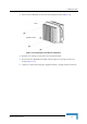


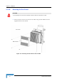
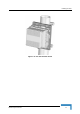
Installing the ODU
4Motion System Manual 59
2.1.5 Connecting the Cables
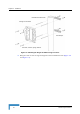
2.1.5.1 Connecting the Grounding Cable
The Grounding screw (marked ) is located on the bottom panel of the outdoor
unit.
1 Connect one end of a grounding cable to the grounding screw and tighten the
grounding screw firmly.
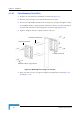
2 Connect the other end of the grounding cable to a good ground (earth)
connection.
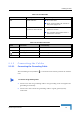
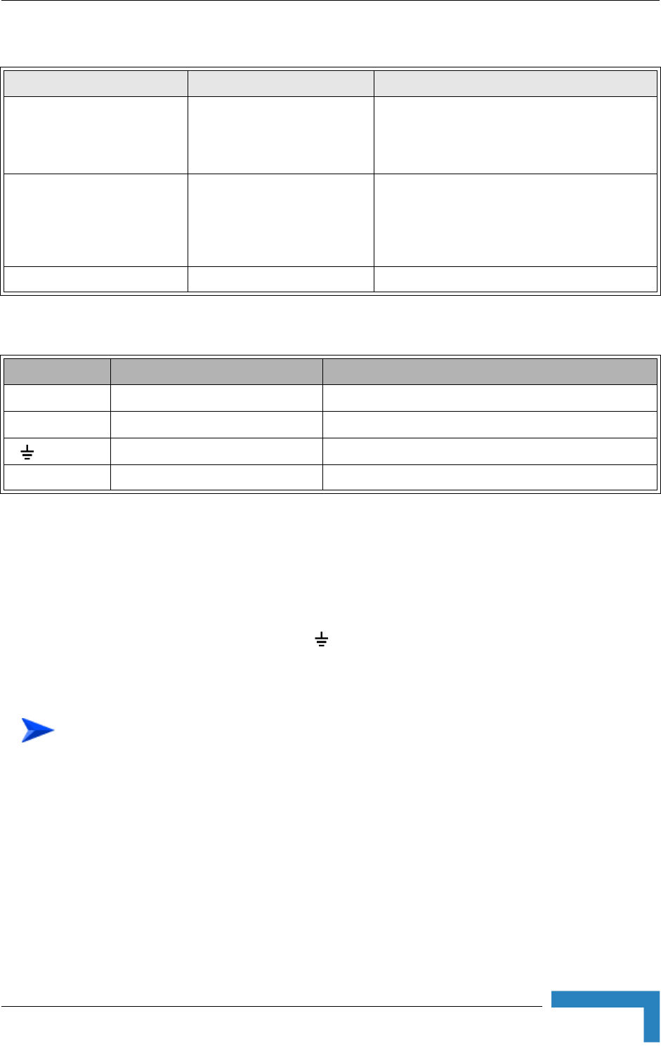
Table 2-5: 4x1 ODU LEDs
Name Description Functionality
PWR Power indication
Off - Power failure
Green - Power to ODU is OK, internal 3.3
VDC power supply is OK.
ALARM AU-ODU communication and
synthesizer status indication
Off - AU-ODU communication is OK,
synthesizer is locked.
Red - AU-ODU communication failure or
synthesizer is not locked
ETH Wireless Link Traffic Green when there is traffic on the wireless link
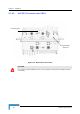
Table 2-6: 4x1 ODU Connectors
Name Connector Functionality
IF-1 to IF-4 4 x TNC jack Connection to the AU/ODU Power Feeder
ANT-1 to ANT-4 4 x N-Type jack, 50 Ohm Connection to an external antenna
(GND) Grounding screw Connection to ground (earth)
CAL-1, CAL-1 Not used in current release
To connect the grounding cable: