
User's Manual
Installing the Base Transceiver Station (BTS) Equipment
4Motion System Manual 69
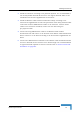
2.3.5.1 Preparing a Power Cable for the PIU
A 2.5m DC power cable is supplied with each chassis. Additional DC cables can
be ordered from Alvarion. If necessary, use the following instruction to prepare a
DC cable.
1 For a cable length up to 2.5m use a cable with 4 x 10AWG (or thicker) wires for
the power plus and an additional 10AWG (or thicker) ground wire. For a longer
cable (up to 10m), use a cable with 4 x 8AWG (or thicker) wires for the power
plus and an additional 10AWG (or thicker) ground wire.
2 The matching power connector to be used is D-SUB 5W5S Female with power
pins 40A.
3 Connect the cable to the power connector as follows:
» Pin 1 (RTN): Red (10/8 AWG min wire)
» Pin 2 (-48V): Black (10/8 AWG min wire)
» Pin 3 ( ): Ground (shield), Green/Yellow (10AWG min wire)
» Pin 4 (-48V): Black (10/8 AWG min wire)
» Pin 5 (RTN): Red (10/8 AWG min wire)
4 Attach suitable terminal rings to the side that connects to the power source.
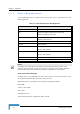
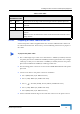
Red Green Power input is out of range or PIU card is damaged. Chassis is powered by the PIU
Green Off Power to PIU is OK. PIU is in redundant mode and the chassis is powered from the
other PIU
Green Green Power to PIU is OK. The chassis is powered from the PIU.
HOT SWAP LED Off: Power from the module to the chassis is not disconnected, the PIU is not ready for
removal
Blue: Power from the module to the chassis can be disconnected and the PIU can be
safely removed
To prepare the power cable:
Table 2-8: PIU LEDs
PWR and
MASTER/ACT LEDs
PIU Status