
User's Manual

Installing the Base Transceiver Station (BTS) Equipment
4Motion System Manual 77
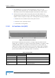
2.3.9 Connecting the BTS Chassis and Modules
The indoor equipment should be installed as close as possible to the location
where the IF cable(s) enters the building. The location of the indoor equipment
should take into account its connection to the power source(s) and to the BTS
networking equipment.
2.3.9.1 Introduction
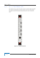
The BTS modules include special handles for high-force insertion/extraction of
modules. Each of the 6U high modules (NPU, AU) includes two such handles,
whereas each of the 3U high-modules (PIU, PSU) includes a single handle at the
bottom of the front panel.
The bottom injector/ejector handle of the NPU and AU modules includes a
micro-switch to support hot-swap control. Second generation PIU modules also
support hot-swap, as indicated by the HOT SWAP blue LED.
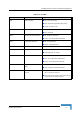
1 Attach the Cable Guide to the top panel of the chassis using the screws and
washers supplied with the Cable Guide.
2 Install the chassis in a 19" cabinet. For installation in a 21" cabinet, attach
suitable ETSI rack adapters to the chassis. To provide a sufficient space for
the Cable Guide and to allow air flow for preventing over-heating, leave a free
space of at least 1U between the upper covers of the chassis and other units in
the cabinet.
3 Connect one end of a grounding cable to the ground terminal located on the
rear panel of the chassis and firmly tighten the grounding screw. Connect the
opposite end of the grounding cable to a ground connection or to the cabinet, if
applicable.
4 Carefully insert the modules into the relevant slots. Secure the modules in
their alloted locations.
5 Place blank covers over all unused slots.
6 Connect the DATA port of the NPU to the backbone data equipment (use a
straight Ethernet cable to connect to a hub/switch/router). The maximum
length of the Ethernet cable is 100m when operating at 100 Mbps and 70m
when operating at 1 Gbps.
To connect the BTS chassis and modules: