
User's Manual

Installing the Base Transceiver Station (BTS) Equipment
4Motion System Manual 79
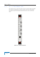
If the red ALRM LED is on while the PWR LED is green, it indicates a failure of at
least one fan. Although the BTS chassis may continue operating with one failed
fan, it is recommended to replace the AVU as soon as possible.
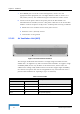
2.3.10 Replacing BTS Components
2.3.10.1 Replacing an AVU
Release the four screws securing the AVU to the chassis.
Using the handle take out the faulty chassis.
Insert a new AVU drawer and tighten the screws.
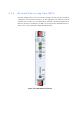
2.3.10.2 Replacing an NPU
To minimize downtime and facilitate fast and easy NPU replacement, it is
recommended to maintain an updated copy of the NPU configuration. Refer to
Section 4.3.4 for details on preparing and uploading a backup file of the NPU
configuration.
1 Release the screws located on the top and bottom of the NPU's front panel.
2 Press the red button of both handles until they are unlocked.
3 Wait until the blue HOT SWAP LED turns on, indicating that the module has
been disconnected and can be removed.
4 Press the upper handle up and the lower handle down until the module is
unlocked. Firmly hold both handles and take the module out of the chassis.
5 Disconnect all IF cables connecting the AUs to the ODUs. This is necessary as
the initial configuration of the new NPU is most probably inappropriate.
6 Firmly push the new NPU module into its intended slot (slot 5).
7 Press the upper handle up and the lower handle down simultaneously until
you hear the locking click and the red buttons are released. The blue HOT
SWAP LED will briefly turn on, indicating that the module is being powered
up.
8 Secure the module in place by tightening the screws located on the top and
bottom of the front panel.
To replace an AVU drawer: