
User's Manual


76 4Motion System Manual
Chapter 2 - Installation
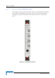
Hot Swap NPU readiness NPU card insertion status indicator
Off: Card is inserted correctly into the chassis
Blue: Card insertion is in progress or is not inserted
successfully
NPU card ejection status indicator
Off: Power to the module is not disconnected, the NPU is
not ready for removal
Blue: Power to the module can be disconnected and the
NPU can be safely removed.
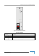
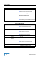
Table 2-13: NPU Connectors
Name Description Function
Data RJ-45 connector
Used to connect the NPU to the backbone
Cable connection to a hub/switch/router: Straight
MGMT RL-45 connector
Connection to out-of-band management
Cable connection to a PC: Crossed
Cable connection to a hub/switch/router: Straight
GP/SYNC IN GPS/SYNC IN connector
Enables connection to a GPS Receiver
GP/SYNC OUT GPS/SYNC OUT
connector
Supply of synchronization signals to another unit (for
future use)
ALRM IN/OUT ALARM IN/OUT
connector
Connection to external alarms
Cascade RJ-45 with two embedded
LEDs
Connection to cascade shelf
Cable connection to local management traffic
Cable connection to cascade shelf: Crossed
MON MON connector
3-pin low profile connector used for accessing the NPU
through the serial command line interface
RESET RESET Button
Used to perform hardware rest to the NPU
Table 2-12: NPU LEDS
Name Description Function