
User Manual

Chapter 2 - Installation Installing the ODU Power Feeder
4Motion 93 System Manual
2.4.2.1 Preparing a Power Cable
A 2.5m DC power cable is supplied with each ODU Power Feeder module.
Additional DC cables can be ordered from Alvarion. If necessary, use the following
instruction to prepare a DC cable.
1 Use a cable capable of supporting a current of at least 10A. Use a cable with
2 x 10AWG (or thicker) wires for the power plus an additional 10AWG to
20AWG ground wire.
2 The matching power connector to be used is Amphenol D-type power P/N
177TWA/3W3/SP3Y with high power socket contacts P/N 17DM53744-1.
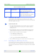
3 Connect the cable to the power connector as follows:
» Pin 1 (RTN): Red (10 AWG min wire)
» Pin 2 (-48V): Black (10 AWG min wire)
» Pin 3 ( ): Ground (shield) (10AWG-20AWG wire)
4 Attach suitable terminal rings to the side that connects to the power source.
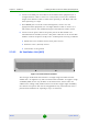
2.4.3 Installing the ODU Power Feeder
The ODU Power Feeder should be installed as close as possible to the location
where the IF cable(s) enters the building. The location of the ODU Power Feeder
should take into consideration its connection to the power source and to the BTS
equipment.
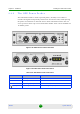
Table 2-17: ODU Power Feeder LEDs
Name Description Functionality
PWR Input power indication
Off - ODU Power Feeder is not powered
Green - ODU Power Feeder power is OK
ODU PWR 1 - 4 Output power indications
Off - ODU is not connected
Red - Power output problem (short or overload)
Green - ODU is connected and powered
To prepare the power cable: