
User's Manual

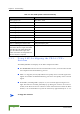


Table Of Contents
- About This Manual
- Contents
- Figures
- Tables
- Chapter 1 - Products Description
- 1.1 BreezeMAX CPEs
- 1.2 Introducing BreezeMAX PRO-S CPE
- 1.3 Introducing BreezeMAX Si CPE
- 1.4 Voice and Networking Gateways
- 1.5 PRO-S CPE Specifications
- 1.6 Si CPE Specifications
- Chapter 2 - Installation
- 2.1 Installing the ODU of the PRO-S CPE
- 2.2 Installing the IDU-1D Indoor Unit of the PRO-S CPE
- 2.3 Installing the Si CPE
- 2.4 Installing the 3.5 GHz Detached Antenna
- 2.5 Installing the 2.3/2.5 GHz Detached Antenna
- Chapter 3 - Commissioning
- Chapter 4 - Operation
- 4.1 The SU Installer Monitor Program
- 4.2 Using the Monitor Program
- 4.3 The Main Menu
- 4.4 Unit Control Menu
- 4.5 Registration Parameters Menu
- 4.6 BST/AU ID Parameters Menu
- 4.7 ˘Radio Parameters Menu
- 4.8 Multirate and ATPC Parameters Menu
- 4.9 Performance Monitoring Menu
- 4.10 FDD Parameters (3.x GHz units only)
- 4.11 ˘SU Parameters Summary
- Appendix A - The Web Configuration Server
- Appendix B - Troubleshooting
- Glossary

70 Commissioning
Chapter 3 - Commissioning
3.3.3 Using SAU for Aligning the PRO-S CPE's
Antenna
The LINK QUALITY bar display on the SAU comprises 9 LEDs:
The WLNK LED indicates that the wireless link is active, and is lit when the SU
has completed the Network Entry process.
LEDs 1 to 8 (green) and 9 (red) indicate the quality of the received signal. The
higher the number of LEDs illuminating, the better the quality of the received
signal.
If all LEDs, including LED 9 (red) are on, the received signal strength is too
high. This must be avoided, preferably by up-tilting the antenna. As a rule of
thumb, if the SU is located at a distance of less than 300 meters from the Base
Station, it is recommended to up-tilt the antenna by approximately 10° to 15°.
Table 3-3: SAU LINK QUALITY LEDs Functionality
Bar LEDs SNR
LED 1 (green) is On 5dB ≤ SNR < 10dB
LEDs 1-2 (green) are On 10dB ≤ SNR < 15dB
LEDs1-3 (green) are On 15dB ≤ SNR < 20dB
LEDs 1-4 (green) are On 20dB ≤ SNR < 24dB
LEDs 1-5 (green) are On SNR ≥ 24dB and RSSI < -75dBm
LEDs 1-6 (green) are On SNR ≥ 24dB and RSSI ≥ -75dBm
LEDs 1-7 (green) are On SNR ≥ 24dB and RSSI ≥ -70dBm
LEDs 1-8 (green) are On SNR ≥ 24dB and RSSI ≥ -60dBm
LEDs 1-8 (green) and 9 (red) are On RSSI ≥ -20dBm (saturation)
LEDs 1 - 8 Blinking one after the other During full frequency scan
LEDs 1 - 9 Blinking as follows: LED 5 lights,
after 200ms LEDs 4 & 6 light, after 200ms
LEDs 3&7 light, after 200ms LEDs 2&8
light, after 200ms LEDs 1 lights, after
200ms all the LEDs are extinguished and
then the sequence is repeated.
During Best AU selection process or short scan
To align the antenna: