
User's Manual

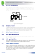
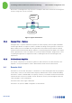
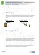
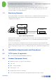


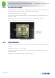
Table Of Contents
- 1 Introduction
- 2 The Concept
- 3 BreezeCELL Architecture
- 4 BreezeCELL Network Elements
- 5 Frequency Allocations
- 6 MIMO Support
- 7 Monitoring & Control
- 8 Installation Requirements and Procedures
- 9 Headend Equipment Installation
- 9.1 Connector Information
- 9.2 Rack Installation
- 9.3 Connecting the BreezeCELL Equipment
- 9.4 Connecting the Monitoring System
- 9.5 Connecting External Alarms
- 9.6 Connecting the Base Stations
- 9.7 UDC Configuration
- 9.8 Pilot Master/Slave Configuration
- 9.9 Measurements
- 9.10 Connecting to the Coax TV Networks
- 9.11 Measurements
- 9.12 Localized Testing Port
- 9.13 Determining BTS Output Power VS. Remote Unit Output Power
- 10 Coax Network Amplifier Installation (if applicable)
- 11 Remote Unit Installation
- 12 Preparing for Remote Unit Installation
- 13 Normal Operations
- 14 Acceptance Testing

In-building Cellular Solution for Commercial Buildings UDC Software Configuration Tool
BreezeCELL
8
The monitoring system provides the user with a user friendly GUI. Using the GUI, the user is able to
send commands to the Remotes (e.g. turning the Remote on and off), query for the status, and
remotely configure (e.g. setting frequencies).
7.1 Monitoring Elements
A proprietary modem is located in the CCD which is able to communicate with all the Remotes. A
similar modem resides in the controller of every Remote which enables the monitoring and
configuration of the Remote.
Figure 7: Monitoring Architecture
The Monitoring PC serial port is connected via an RS-232 cable to the CCD. The user has a Web based
GUI and the PC translates the user operations into a set of commands transmitted by the modems
between the PC and Remotes.
The PC polls all the Remotes at regular intervals to check their operational status and updates the
database with the changes. The Remotes constantly monitor their internal status. In case of a fault the
Remote will transmit a message to the PC to indicate the fault. The PC will update the database and
GUI.
8 Installation Requirements and Procedures
8.1 CATV System (if applicable)
Coax TV plant supporting 750/860MHz transmissions
8.2 Headend (Equipment Room)
Equipment room 19” rack space for the following:
CCD – 2 U
UDC – 1 U (for each UDC)
monitoring PC – 1 U
Available power outlets for CCD, UDCs,
Socket outlets should be installed near the equipment and shall be easily accessible
CCD
Modem
RS-232
UDC
Remote
Modem
RF + Monitoring signal
RF