
User's Manual

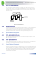


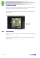
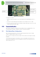
Table Of Contents
- 1 Introduction
- 2 The Concept
- 3 BreezeCELL Architecture
- 4 BreezeCELL Network Elements
- 5 Frequency Allocations
- 6 MIMO Support
- 7 Monitoring & Control
- 8 Installation Requirements and Procedures
- 9 Headend Equipment Installation
- 9.1 Connector Information
- 9.2 Rack Installation
- 9.3 Connecting the BreezeCELL Equipment
- 9.4 Connecting the Monitoring System
- 9.5 Connecting External Alarms
- 9.6 Connecting the Base Stations
- 9.7 UDC Configuration
- 9.8 Pilot Master/Slave Configuration
- 9.9 Measurements
- 9.10 Connecting to the Coax TV Networks
- 9.11 Measurements
- 9.12 Localized Testing Port
- 9.13 Determining BTS Output Power VS. Remote Unit Output Power
- 10 Coax Network Amplifier Installation (if applicable)
- 11 Remote Unit Installation
- 12 Preparing for Remote Unit Installation
- 13 Normal Operations
- 14 Acceptance Testing

In-building Cellular Solution for Commercial Buildings UDC Software Configuration Tool
BreezeCELL
12
9.7.1 BTS Attenuation Setting
The UDC input power is limited. An internal attenuator allows inputs of +10 dBm to +33 dBm. In case
the output is larger a separate attenuator on the downlink only is required.
Switches represent values of: 1, 2, 4, 8, 16 dB.
The left most switch has the highest attenuation – 16 dB. The right most switch represents the least
attenuation – 1 dB.
The output level of the downlink cellular signal in the Alvarion band should be 0±1 dBm.
The following figure demonstrates the location of the attenuator:
Figure 10: BTS Attenuator
9.7.2 Gain Configuration
The UDC has internal attenuators that allow you to control the Pilot signal level and up link and down
link gains
Switches represent values of: 1, 2, 4, 8, 16 dB.
The left most switch has the highest attenuation – 16 dB. The right most switch represents the least
attenuation – 1 dB.
All signals are pre-configured according to network parameters.