
User's Manual


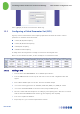
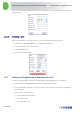
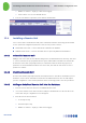
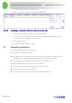
Table Of Contents
- 1 Introduction
- 2 The Concept
- 3 BreezeCELL Architecture
- 4 BreezeCELL Network Elements
- 5 Frequency Allocations
- 6 MIMO Support
- 7 Monitoring & Control
- 8 Installation Requirements and Procedures
- 9 Headend Equipment Installation
- 9.1 Connector Information
- 9.2 Rack Installation
- 9.3 Connecting the BreezeCELL Equipment
- 9.4 Connecting the Monitoring System
- 9.5 Connecting External Alarms
- 9.6 Connecting the Base Stations
- 9.7 UDC Configuration
- 9.8 Pilot Master/Slave Configuration
- 9.9 Measurements
- 9.10 Connecting to the Coax TV Networks
- 9.11 Measurements
- 9.12 Localized Testing Port
- 9.13 Determining BTS Output Power VS. Remote Unit Output Power
- 10 Coax Network Amplifier Installation (if applicable)
- 11 Remote Unit Installation
- 12 Preparing for Remote Unit Installation
- 13 Normal Operations
- 14 Acceptance Testing

In-building Cellular Solution for Commercial Buildings UDC Software Configuration Tool
BreezeCELL
15
8. The diplexer CABLE port now carries the combined TV and wireless signal. Connect the CABLE port
the to the building coax network input
Note: The diplexer AC port will be in use only when the coax network is self powered by a 60 VAC
source.
9.11 Measurements
Use a spectrum analyzer to verify that the CABLE output of the diplexer includes the cellular, pilot and
TV signals at their respective power levels as measured in sections
7.9 and 7.10.
9.12 Localized Testing Port
The CCD is equipped with an ability to locally test the BTS connectivity and proper remote unit
operation. The RF Output Monitoring connector in the front of the CCD is a output that is similar to the
CCD RF Output with a -40 dB attenuation. A remote unit can be directly connected to this output to
test the BTS output without the need to disrupt the coax plant.
9.13 Determining BTS Output Power VS. Remote Unit Output
Power
BreezeCELL remote units are offered with two output power settings: 0 dBm and 10 dBm. The remote
unit output power setting is per carrier. The system maintains constant linear gain between the BTS and
the remote unit, thus enabling the BTS/MS power control mechanism to operate normally. The BTS
power output should be configured not to exceed the UDC input power specification.
Example:
GSM BTS with a 46 dBm output power.
External downlink attenuation between BTS and UDC (Attenuation at UDC input)
UDC internal attenuation set at 20 dB
Remote unit output power 10 dBm (per carrier)
GSM BCCH is measured at 0 dBm at the output of the UDC
Number of
Carriers
Attenuation at UDC
Input [dB]
UDC Output
[dBm]
Remote Unit
Output Power
[dBm]
1 26 0 10
2 23 3 13
4 20 6 16
8 17 9 19