
User's Manual


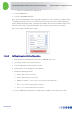
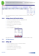
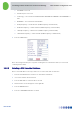
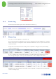
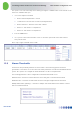
Table Of Contents
- 1 Introduction
- 2 The Concept
- 3 BreezeCELL Architecture
- 4 BreezeCELL Network Elements
- 5 Frequency Allocations
- 6 MIMO Support
- 7 Monitoring & Control
- 8 Installation Requirements and Procedures
- 9 Headend Equipment Installation
- 9.1 Connector Information
- 9.2 Rack Installation
- 9.3 Connecting the BreezeCELL Equipment
- 9.4 Connecting the Monitoring System
- 9.5 Connecting External Alarms
- 9.6 Connecting the Base Stations
- 9.7 UDC Configuration
- 9.8 Pilot Master/Slave Configuration
- 9.9 Measurements
- 9.10 Connecting to the Coax TV Networks
- 9.11 Measurements
- 9.12 Localized Testing Port
- 9.13 Determining BTS Output Power VS. Remote Unit Output Power
- 10 Coax Network Amplifier Installation (if applicable)
- 11 Remote Unit Installation
- 12 Preparing for Remote Unit Installation
- 13 Normal Operations
- 14 Acceptance Testing

In-building Cellular Solution for Commercial Buildings UDC Software Configuration Tool
BreezeCELL
24
13.1 Logging into the Monitoring System
Upon activation of the system, the user will be directed to the entry screen and prompted to enter User
Name and User Password. Enter the login information to enter the system.
After logging in the main screen will be the Alarms Log
13.2 The Status Bar
On the top of the screen there is a status bar which remains visible in all the screens. The Status Bar
provides immediately available information for the operator regarding:
Number of Operational remote units
Number of Uninstalled remote units
Number of Undefined remote units
Number of Failed remote units
Number of Active Alarms
13.3 Viewing Remote Units Status
The operator can view a list of all operational remote units status and configuration or alternatively look
at a single remote unit.