
User's Manual


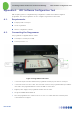

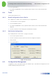


Table Of Contents
- 1 Introduction
- 2 The Concept
- 3 BreezeCELL Architecture
- 4 BreezeCELL Network Elements
- 5 Frequency Allocations
- 6 MIMO Support
- 7 Monitoring & Control
- 8 Installation Requirements and Procedures
- 9 Headend Equipment Installation
- 9.1 Connector Information
- 9.2 Rack Installation
- 9.3 Connecting the BreezeCELL Equipment
- 9.4 Connecting the Monitoring System
- 9.5 Connecting External Alarms
- 9.6 Connecting the Base Stations
- 9.7 UDC Configuration
- 9.8 Pilot Master/Slave Configuration
- 9.9 Measurements
- 9.10 Connecting to the Coax TV Networks
- 9.11 Measurements
- 9.12 Localized Testing Port
- 9.13 Determining BTS Output Power VS. Remote Unit Output Power
- 10 Coax Network Amplifier Installation (if applicable)
- 11 Remote Unit Installation
- 12 Preparing for Remote Unit Installation
- 13 Normal Operations
- 14 Acceptance Testing

In-building Cellular Solution for Commercial Buildings UDC Software Configuration Tool
BreezeCELL
38
Appendix A. UDC Software Configuration Tool
UDC frequency plans are configurable using configuration software and a Alvarion supplied
programmer. The same programmer can also configure 1st generation remote units.
A.1. Requirements
PC/Laptop with a serial port
ICP-01 Programmer
Alvarion configuration software
A.2. Connecting the Programmer
The programmer is supplied with two cables:
Serial 9 pin to Serial 9 pin (or USB)
Serial 15 pin to RJ – 11
Figure 16: Programmer Connection
1. Connect the 9 pin serial cable between the programmer serial 9 pin port and a PC serial port
2. Connect the serial 15 to RJ-11 cable. The serial side connects to the programmer data port and the
other side to the programmed device such as the UDC or remote unit.
3. Plug the power supply to the programmer and into the AC mains.
4. The green POWER LED should be lit
5. Note: the programmer uses COM1 on the PC. In case of a conflict with other software please
contact Alvarion for support.