BreezeNET PRO.11 Series Outdoor Bridge User’s Guide (for models using AMP2400S-250/500) October, 2000 Cat. No.
Disclaimer: The diagrams in this manual are for illustrative purposes only. They should not be confused with the transceiver operating in a standalone mode. When these diagrams are in use, the transceiver will be installed in conjunction with amp model AMP-2400S-250/500 and the antennas listed in Table 1. © 2000 by BreezeCOM Ltd. All rights reserved. No part of this publication may be reproduced in any material form without the written permission of the copyright owner.
Statement of Conditions The information contained in this manual is subject to change without notice. BreezeCOM Ltd. shall not be liable for errors contained herein or for incidental or consequential damages in connection with the furnishing, performance, or use of this manual or equipment supplied with it. Warranty In the following warranty text, “the Company” shall mean: - BreezeCOM Inc., for products located in the USA. - BreezeCOM Ltd., for products located outside the USA.
limits of these regulations and to ensure that only professional installers install this device that are aware of these regulations and trained or recommended by Breezecom, as well. " FCC Radiation Exposure Statement i) This equipment complies with FCC radiation exposure limits set forth for an uncontrolled environment when installed as directed.
CONTACTING BREEZECOM TECHNICAL SUPPORT Should you need assistance beyond the scope of this guide, please contact your local BreezeCOM reseller or distributor. If they cannot solve your problem, feel free to contact the BreezeCOM Technical Support Department. The support representatives can assist you in solving any problems that cannot be solved by your reseller.
Introduction To The BreezeNET PRO.11 Series TABLE OF CONTENTS 1. Introduction To The BreezeNET PRO.11 Series ....................................... 1-4 1.1. How to Use This Guide ............................................................................ 1-4 1.2. BreezeNET PRO.11 Series Features ........................................................ 1-5 1.2.1. Access Point ................................................................................. 1-6 1.2.2. Workgroup Bridge .....................
Introduction To The BreezeNET PRO.11 Series 3.5.7. Maintenance............................................................................ 3-1618 3.6. Site Survey Menu ............................................................................... 3-1719 3.6.1. System Counters.................................................................... 3-1819 3.6.2. Survey Software .................................................................... 3-2223 3.6.3. Event Log ..........................................
Introduction To The BreezeNET PRO.11 Series 8. Appendix 9-1 8.1. Supported MIBs and Traps....................................................................... 9-1 8.1.1. Supported MIBs............................................................................ 9-1 8.1.2. Supported Traps............................................................................ 9-2 8.2. Technical Specifications........................................................................... 9-3 8.2.1.
Introduction To The BreezeNET PRO.11 Series 1. INTRODUCTION TO THE BREEZENET PRO.11 SERIES This chapter explains how to use this guide, presents the members of the BreezeNET PRO.11 Series, describes the benefits of BreezeNET PRO.11 Wireless LANs, and lists the product specifications. 1.1. How to Use This Guide This User’s Guide contains instructions for overall planning and setting up your wireless LAN, and provides details of how to install each unit, and how to install antennas and accessories.
Introduction To The BreezeNET PRO.11 Series 1.2. BreezeNET PRO.11 Series Features Following is a partial list of the features in the BreezeNET PRO.11 Series: • IEEE 802.11 Compliant – All BreezeNET PRO.11 Series units are fully compliant with the final IEEE 802.11 specification for wireless LANs, and thus support interoperability with other 802.11 compliant vendors. • Fully integrated product family – One high-performance Access Point for all products in the series.
Introduction To The BreezeNET PRO.11 Series 1.2.1. Access Point The Access Point is fully compliant with the IEEE 802.11 wireless LAN standard. The BreezeNET Access Point is a wireless hub that provides access for wireless workstations into wired Ethernet LANs.
Introduction To The BreezeNET PRO.11 Series Balancing algorithm to divide the stations equally between the available colocated Access Points. The BreezeNET Access Point contains an embedded SNMP agent enabling effective management by BreezeVIEW or any standard SNMP management station. Software upgrades can be downloaded by TFTP protocol via the wired LAN or wireless LAN. 1.2.2.
Introduction To The BreezeNET PRO.11 Series orkstations that can be connected to the wireless LAN include PCs, XTerminals, Digital, SUN, HP, IBM, and Apple computers, and any other device that supports Ethernet. The unit is transparent to the workgroup devices’ hardware, software, and network operating system. The BreezeNET Workgroup Bridge contains an embedded SNMP agent and software downloading capabilities enabling effective management.
Introduction To The BreezeNET PRO.11 Series 1.4. Antenna Selection The AMP2400S and the BreezeNET radio modem must be professionally installed. Table (1) shows the FCC approved configuration of the AMP2400S, BreezeNET Radio and antenna configurations. WARNING: It is the responsibility of the installer to ensure that when used in the United States (or where FCC rules apply), only these configurations are used.
Introduction To The BreezeNET PRO.11 Series 1.5. BreezeNET PRO.11 Functional Description BreezeNET PRO.11 units add wireless functionality to existing Ethernet LANs. 1.5.1. Quick Review of Ethernet Standard Ethernet LAN stations are wired to a common bus. When one of the stations sends a message, it assigns a destination address to the message and sends the message on the bus. All stations on the bus “hear” the message, but only the station with the proper address processes the message. 1.5.2.
Introduction To The BreezeNET PRO.11 Series 1.5.4. SA-10 Station Adapter The SA-10 station adapter is connected to a station’s network card. When the station sends a message, the SA-10 wirelessly forwards it to the AP-10. And when the AP-10 receives a message destined for the station, it wirelessly forwards the message to the SA-10. The first time the station sends a message, the station’s address is registered in the AP-10.
Basic Installation 2. BASIC INSTALLATION The BreezeNET PRO.11 Series is a plug-and-play solution, and the units begin to function when the following basic installation is complete. However, you can adapt the system to your particular needs using the local terminal (see Chapter 3). For a description of various overall system configurations, refer to Chapter 4. 2.1. Basic Installation Checklist Standard installation involves the following steps: • Check the Package List.
Basic Installation The AP-10 PRO.11 Access Point comes with the following additional components: • The BreezeNET PRO.11 Series User’s Guide. • A monitor connector cable for connecting the units to a monitor in order to perform Local Terminal Management functions (see section 3.1). • Proprietary MIB disk for performing remote unit configuration and monitoring via SNMP (see section 8.1.1). Open the packaging carefully and make sure that none of the items listed above are missing.
Basic Installation Outdoor Installation Considerations. Heat Sources Keep the units well away from sources of heat, such as radiators, airconditioners, etc. 2.3.1. Additional Considerations When Positioning the Access Point When positioning the AP-10 PRO.11 and AP-10DE Access Points, take into account the following additional considerations. Height Install the Access Point at least 1.5m above the floor, clear of any high office partitions or tall pieces of furniture in the coverage area.
Basic Installation • Plug the output jack of the power transformer into the DC input socket on the unit. This socket may be located on the rear or side panel of the unit. • Connect the supplied power transformer to a power outlet 110/ 220VAC. 2.5. Connect the Unit to the Ethernet Port • Connect one end of a an Ethernet 10BaseT cable (not supplied) to the RJ-45 port on the rear panel of the unit (marked UTP).
Basic Installation 2.6. Check Unit Functionality using LED indicators Check the unit functionality by using the LEDs on the front panel. The following tables describe the front panel LEDs for Stations (SA-10, SA-40) and Bridges (WB-10), and for Access Points. 2.6.1.
Basic Installation 2.6.2.
Device Setup and Management 3. DEVICE SETUP AND MANAGEMENT This chapter explains how to access the local terminal program, and how to use the terminal program to setup, configure, and manage most BreezeNET PRO.11 Series units. The BreezeNET PRO.11 Series is a plug-and-play solution and operates immediately after physical installation without any user intervention. However, you can adapt the system to your particular needs using the local terminal.
Device Setup and Management Þ To use Local Terminal Management: 1. Press an option number to open/activate the option. You may need to press Enter in some cases. 2. Press Esc to exit a menu or option. 3. Reset the unit after making configuration changes. 3.2. Configuration Screens Listed below are the menus, sub-menus, and parameters/options in the terminal program. Default values are listed where applicable. Numbers in the table below indicate how to reach each option. For example, to reach the 1.2.
Device Setup and Management Menu Sub-Menu Parameter/Option 1.5 Station Control 1.5.1 Reset Unit 1.5.2 Load Factory Defaults 1.6.Security 1.6.1 Authentication Algorithm 1.6.2 Default Key ID 1.6.3 Preauthentication A. WEP Default Key #1 B WEP Default Key #2 C. WEP Default Key #3 D. WEP Default Key #4 (Not activated) 2. Advanced Settings 2.1 Translation Mode Open System Key #1 Disabled User defined User defined User defined User defined Enabled 2.2.1 Max Number of Scanning 2.2.
Device Setup and Management Menu Sub-Menu Parameter/Option 3.2.3 Stop Statistics Default Values 3.3 Event Log 3.3.1 Display Event Log 3.3.2 Erase Event Log 3.3.3 Event Storage Policy From level warning up 3.4 Display Neighboring AP’s 4. Access Control 4.1 Change Access Rights 4.2 Change Installer Password 4.3 Show Current Access Right * Option 1.3.5 Transmit Antenna has the default value Use #2 for the SA-40 unit only. ** Option 1.3.
Device Setup and Management 3.4. System Configuration Menu BreezeNET PRO.11 Series (SA-10) Version : 4.3.10 Date: 15 Feb 1999 23:49:56 System Configuration menu ========================= 1 - Station Status 2 - IP and SNMP Parameters 3 - Wireless LAN Parameters 4 – Bridging 5 - Station Control 6 – Security Select option > Figure 3.2: System Configuration Menu 3.4.1.
Device Setup and Management • Sync Waiting for Address - (this option is relevant only to the SA10). The station is synchronized with an AP but has not yet learned its WLAN MAC address. The AP does not forward packets to the station when it is in this mode. • Associated - The station is associated with an AP and has adopted the attached PC MAC address (for SA-10) or uses the unit’s H/W address (SA-40 and WB-10), and is receiving packets from the LAN.
Device Setup and Management • SNMP Traps – Whether this unit sends SNMP traps. If enabled, when an event occurs, a trap is sent to the defined host address (see section 8.1.2 for a list of traps). You can configure the host address to which the traps are sent through SNMP management. • Display Current Values – Displays information concerning the current status of all IP-related items. 3.4.3.
Device Setup and Management Hopping Sequence=1, Hopping Set=1. • ESSID – ESSID of the unit (up to 32 printable ASCII characters). The ESSID is a string used to identify a WLAN. This ID prevents the unintentional merging of two co-located WLANs. A station can only associate with an AP that has the same ESSID. Use different ESSIDs to segment the WLAN network and add security. Note: The ESSID is case-sensitive. • Maximum Data Rate – Maximum data rate of the unit. BreezeNET PRO.
Device Setup and Management • Medium – For stations that may move at speeds of over 10 km per hour, but not over 30 km per hour. • Low – For stations that will not move at speeds of over 10 km per hour. Low is the default value. In most cases this is the best choice. • Load Sharing – When installing a Wireless LAN network in a hightraffic environment; you can increase the aggregate throughput by installing multiple APs to create co-located cells.
Device Setup and Management (except that no learning of the wired LAN will take place). Afterwards, the AP will switch back to Reject Unknown bridging mode. This procedure prevents packets destined for stations behind the bridge from getting lost. The value of this parameter is the length of time in seconds that the AP will remain in special mode. • IP Filtering – Whether IP filtering is enabled for the unit.
Device Setup and Management • Reset Unit – Resets the BreezeNET PRO.11 unit and applies any changes made to the system parameters. • Set Factory Defaults –When this option is implemented, system parameters revert back to the original factory default settings. There are two options: • Full – All parameters revert to defaults except for the Hopping Standard and Japan Call Sign (if applicable).
Device Setup and Management • • Preauthentication – During the authentication process the AP is notifying the other AP’s connected to the Ethernet backbone to preauthenticate the station that has been authenticated to this AP. It is recommended to use this feature when there is plenty of roaming between the AP’s. Preauthentication must be activated on both the AP’s and the Station. WEP Key#1-4 – These 4 Access Keys must be configured before they can be used.
Device Setup and Management 3.5.1. Translation Mode (read-only) The translation of Ethernet packets can be enabled (default) or disable. 3.5.2. Roaming (read-only) The Roaming menu contains parameters related to when and how the unit roams from one AP to another. The following windows can be accessed from the Roaming menu: • • • · · • • • • 3.5.3. Max.
Device Setup and Management this menu, Max. Number of Re-Transmissions and Number of Dwells to Re-Transmit. This parameter can be presented as a counter. This counter is decreased each time a re-transmission occurs. It will be the minimum number of times a packet will be re-transmitted. • Number of Dwells to Re-Transmit (read-only) – A re-transmission will be performed after a set number of Dwells. This parameter works in conjunction with the Max Number of Re-Transmissions parameter.
Device Setup and Management This process is done every 2 seconds. Notice that although power save mode is set in the AP it will not effect the APs’ power consumption, but only the handling and management. • DTIM Period (read-only) – This is the number of dwells between broadcast transmissions of messages for stations in power saving mode. Note: This option is not activated yet. • IP Stack – By default this parameter is enabled.
Device Setup and Management Sense mechanism. Signals with a lower RSSI are considered “noise” and are disregarded by the unit. • 3.5.5. Carrier Sense Difference Level (read-only) - Carrier Sense Difference Level refers to a sudden rise of the signal level. This parameter is the minimum rise in RSSI units to be considered a Carrier Sense postitive result, in which case the unit will not attempt to transmit.
Device Setup and Management Association Address update over the Ethernet. You can also have the device use its own MAC address (Use Mine) for testing purposes, in which case there will not be a proper network connection. 3.6. Site Survey Menu BreezeNET PRO.11 Series (SA-10) Version : 4.3.10 Date: 15 Feb 1999 23:49:56 Site Survey menu ================ 1 - System Counters 2 - Survey Software 3 – Event Log 4 – Display Neighboring AP’s Select option > Figure 3.
Device Setup and Management 3.6.1. System Counters BreezeNET PRO.11 Series (AP-10) Version : 4.3.10 Date: 15 Feb 1999 23:49:56 System Counters menu ==================== 1 - Display Ethernet and WLAN Counters 2 - Display Rate Counters 3 - Display Rx packets per frequency 4 - Reset All Counters 5 - Power Saving Counters Select option > Figure 3.4b: Systems Counters Menu The System counters are a simple yet very efficient tool to monitor, interpret and analyze the Wireless LAN performance.
Device Setup and Management • Received Bad Frames – The number of frames with errors received from the UTP port. High values (more than just a few) indicate a problem in the UTP connection such as a bad UTP cable or hub port. • Received good frames – The number of good frames (i.e. frames with no errors) received from the UTP port. • Forwarded to the bridge – The number of received frames that were forwarded to the unit’s internal bridge.
Device Setup and Management transmitted frames counter will get high values even if the AP-10 is not connected to an active LAN. • Total Transmitted Frames (Bridge) - The total number of data frames transmitted to the wireless media (i.e. frames that were received form the UTP port and forwarded to the internal bridge which decided to transmit them to the wireless media). • Total Transmitted Data Frames – This counter is similar to the above but counts only data frames. In most BreezeNET PRO.
Device Setup and Management • Power Saving Free Entries – Number of free buffers (one frame each) available for power save management. These buffers hold messages for stations that only periodically make contact with the AP due to power considerations. • Total Received Frames - The number of frames received from the wireless media. The count includes data and control frames (including beacons received from AP’s).
Device Setup and Management 3.6.2. Survey Software The Survey Software sub-menu enables you to align antennas and to assess the radio signal quality of a point-to-point link. The sub-menu includes the following options: • Operation Mode – When running a Site Survey, set the units on either side of the link to either receive (option 1) or transmit (option 2) packets (one unit should be set to transmit and the other to receive). Option 0 (Idle mode) is not active at present.
Device Setup and Management • Total: The number of frames set as the “Roaming Decision Window” 10 in the example shown above (see “Roaming” on section 3.5.2). • avr RSSI: The average RSSI level of the total number of frames (only includes the frames received without errors). • bcn cnt: (Beacon Count) - How many dwells have passed since the last beacon has been received. • Load: The number of stations currently associated with the descried AP.
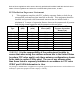
Device Setup and Management BreezeNET PRO.11 Series (AP-10) Version : 4.3.10 Date: 15 Feb 1999 23:49:56 # Tx Packets Channel 0 37 1 10 2 7 3 30 4 28 5 44 6 35 7 12 8 48 9 76 10 42 Figure 3.5: Transmit Statistics 6.
Device Setup and Management Version : 4.3.10 Date: 15 Feb 1999 23:49:56 #Pack Ant RSSI1 RSSI2 Bit_Err Freq Rate Quality 58 1 108 91 0 19 3 ########### 59 2 110 112 0 42 3 ########### 60 2 86 88 0 14 3 ########...
Device Setup and Management 9. Switch the functions of either side of the link (set the transmit unit to receive and the receive unit to transmit) and repeat the procedure to check the link from the opposite direction. 3.6.6. Using the Rx Packets per Frequency Histogram Use the Display Rx Packets per Frequency option to see a histogram of the number of frames received on each channel. BreezeNET PRO.11 Series (AP-10) Version : 4.3.
Device Setup and Management interference. Frequencies with low numbers of packets received probably have more interference than other frequencies. 3.7. Access Control Menu Access Control functions enable the System Administrator or Installer to limit the access to the Local Terminal Maintenance setup and configuration menus. BreezeNET PRO.11 Series (AP-10) Version : 4.3.
configuration, the installer should change access rights to option (0), User. The installer can also change the installer password (see next parameter). • Technician – Only a Certified BreezeCOM Engineer possessing the correct password can select this option to configure all the parameters and settings. • Change Installer Password – Type in the new password according to the directions on screen.
Planning and Installing Wireless LANs 4. PLANNING AND INSTALLING WIRELESS LANS This chapter describes various possible system configurations, lists points to consider when performing indoor and outdoor installations, presents guidelines and restrictions regarding external antenna installation. It also describes some antennas that work well with BreezeNET PRO.11 units. 4.1.
Planning and Installing Wireless LANs 4.1.1. Single Cell Configuration A basic BreezeNET cell consists of an Access Point and the wireless workstations associated with it. You can convert most workstations (PCs, X-Terminals, Apple, Digital, SUN, HP, IBM and others) that are equipped with an Ethernet network interface card (NIC) to wireless workstations simply by connecting a BreezeNET SA-10 PRO.11 Station Adapter.
Planning and Installing Wireless LANs The remote units should use directional antennas aimed in the direction of the AP’s antenna(s). 4.1.1.3 Mobile Applications In mobile applications, station orientation changes continuously. In order to maintain connectivity throughout the entire coverage area, most mobile applications require omni-directional antennas for both Access Points and wireless stations. In a motor vehicle, for example, you can install an SA-10 in the cabin, and mount the antennas on the roof.
Planning and Installing Wireless LANs The WB-10 PRO.11 also enables connectivity between a wireless LAN and individual workstations or workgroups located outside the LAN. The WB-10 PRO.11 enables these wireless stations in its coverage area to communicate with the wireless LAN and gain access to all of the network resources such as file servers, printers and shared databases. Figure 5.2: Wireless Bridging Between Two or More Wireless LAN Segments 4.1.1.
Planning and Installing Wireless LANs • Adjust the antennas • Adjust the location of the Station Adapter • Adjust the location of the Access Point 5. Proceed to setup the other workstations. Figure 5.3: Single Cell Configuration Disclaimer: This diagram is for illustrative purposes only. It should not be confused with the transceiver operating in a standalone mode.
Planning and Installing Wireless LANs 4.1.2. Overlapping Cell Configuration When two adjacent Access Points are positioned close enough to each other, a part of the coverage area of Access Point #1 overlaps that of Access Point #2. This overlapping area has two very important attributes: • Any workstation situated in the overlapping area can associate and communicate with either Access Point #1 or Access Point #2.
Planning and Installing Wireless LANs 5. Install a Station Adapter or SA-PCR Card on a workstation. 6. Position the wireless workstation approximately the same distance from the two Access Points. 7. Temporarily disconnect the first Access Point from the power supply. Verify radio signal reception from the first Access Point. View the LED indicators of the front panel of the Station Adapter, or the Site Survey application of the SA-PCR Card, to check signal strength of the first Access Point. 8.
Planning and Installing Wireless LANs 4.1.3. Multicell Configuration Areas congested by many users and a heavy traffic load may require a multicell structure. In a multicell structure, several Access Points are installed in the same location. Each Access Point has the same coverage area, thereby creating a common coverage area that increases aggregate throughput. Any workstation in the overlapping area can associate and communicate with any Access Point covering that area.
Planning and Installing Wireless LANs Note: It is not necessary at this point to connect the Access Points to an Ethernet backbone, since Access Points continuously transmit signals (beacon frames) whether they are connected to an Ethernet backbone or not. Figure 5.5: Multicell Configuration BreezeNET PRO.
Planning and Installing Wireless LANs 4.1.4. Multi-hop Configuration (Relay) When you want to connect two sites between which a line-of-sight does not exist, an AP-WB pair can be positioned at a third location where line-ofsight exists with each of the original locations. This third location then acts as a relay point. In areas where a wired LAN backbone is not available, another AP can be added to the AP-WB relay to distribute a wireless backbone.
Planning and Installing Wireless LANs Figure 5.6: Multihop Configuration 6. If desired, an additional AP may be added at the main office and remote site, and between each AP-WB pair to provide wireless LANs at those points (see illustration). Figure 5.7: Advanced Multihop Configuration 7. Install Station Adapters or SA-PCR Cards on workstations (refer to section 2, Basic Installation). BreezeNET PRO.
Planning and Installing Wireless LANs 4.2. Outdoor Installation Considerations This chapter describes various considerations to take into account when planning an outdoor installation including site selection, antenna alignment, antenna diversity, antenna polarization, antenna seal, and cell size. 4.2.1.
Planning and Installing Wireless LANs Minimal Path Loss Path loss is determined mainly by several factors: • Distance between sites Path loss is lower and system performance better when distances between sites are shorter. • Clearance Path loss is minimized when there exists a clear line of sight. The number, location, size, and makeup of obstacles determine their contribution to path loss. • Antenna height Path loss is lower when antennas are positioned higher.
Planning and Installing Wireless LANs 4.2.3.1 Point-to-Point A point-to-point link is based on the use of one Access Point with external antennas and one adapter (SA-10/40D, WB-10D). The AP and the WB must be equipped with one or two directional antennas. The necessary antenna gain depends on the required range and performance. 4.2.3.
Planning and Installing Wireless LANs If the received signal quality is lower than expected for this antenna/range combination, change antenna height and verify RF cables connections. 4.2.3.4 Antenna Diversity In applications where no multipath propagation is expected, a single antenna is sufficient to ensure good performance levels. However, in cases where multipath propagation exists, BreezeCOM recommends that two antennas be used. This takes advantage of space diversity capabilities.
Planning and Installing Wireless LANs PRO.11 workstation, the suggested maximum distance between Access Point and workstation is: Standard AP-10 PRO.11 ..........................700m (2000 ft.) 4.2.6. Link Distance Link distance is the maximum distance between the AP and the station adapter, usually related to point-to-point installations using external antennas.
Planning and Installing Wireless LANs 4.3. Precautions 4.3.1. Professional Installers Only Caution: Detached antennas, whether installed indoors or out, should be installed ONLY by experienced antenna installation professionals who are familiar with local building and safety codes and, wherever applicable, are licensed by the appropriate government regulatory authorities. Failure to do so may void the BreezeNET Product Warranty and may expose the end user to legal and financial liabilities.
Planning and Installing Wireless LANs devices. A building can withstand up to 100,000 volts, but electronic equipment may be damaged by just a few volts. Lightning protection entails connecting an antenna discharge unit (also called an arrestor) to each cable as close as possible to the point where it enters the building. It also entails proper grounding of the arrestors and of the antenna mast (if the antenna is connected to one).