BreezeACCESS Base Station Equipment Installation Manual February, 2001 Cat. No.
Front Matter © 2001 by BreezeCOM Ltd. All rights reserved. No part of this publication may be reproduced in any material form without the written permission of the copyright owner. Trade Names BreezeACCESS, BreezeNET, BreezeLINK, BreezeVIEW and BreezeMANAGE are trade names of BreezeCOM Ltd. Other brand and product names are registered trademarks or trademarks of their respective companies. Statement of Conditions The information contained in this manual is subject to change without notice.
Front Matter Limitations of Warranty The foregoing warranty shall not apply to defects resulting from improper or inadequate maintenance by the buyer, buyer supplied interfacing, unauthorized modification or misuse, operation outside of the environmental specifications for the product, or improper site preparation or maintenance. No other warranty is expressed or implied. The Company specifically disclaims the implied warranties of merchantability and fitness for any particular purpose.
Front Matter R&TTE Compliance Statement This equipment complies with the appropriate essential requirements of Article 3 of the R&TTE Directive 1999/5/EC. Information to User Any changes or modifications of equipment not expressly approved by the manufacturer could void the user’s authority to operate the equipment. Safety Considerations For the following safety considerations, “Instrument” means the BreezeACCESS Base Station equipment components and cables.
Table of Contents Table of Contents 1. INTRODUCTION............................................................................................................ 1 2. BASIC INSTALLATION................................................................................................. 3 2.1 Packing List – Modular Shelf Equipment........................................................................ 3 2.1.1 BS-SH Base Station Shelf.................................................................................
Table of Contents 4. VERIFYING CORRECT OPERATION........................................................................ 24 4.1 Verifying Correct Operation of the AU-A/E-BS............................................................ 24 4.2 Verifying Correct Operation of the AU-A/E-NI............................................................. 24 4.3 Verifying Correct Operation of the Outdoor Unit .......................................................... 25 5. SPECIFICATIONS...............................
Table of Figures Table of Figures Figure 2-1. Holes/Grooves/Screw Holes ............................................................................ 7 Figure 2-2. AU-RE 3" Pole Mounting Installation Using the Special Brackets ...................... 8 Figure 2-3. BreezeACCESS II and BreezeACCESS MMDS AU-RA/AU-RE Radio Unit Bottom Panel .................................................................................................................... 9 Figure 2-4.
Introduction 1. INTRODUCTION This manual describes installation guidelines for BreezeACCESS base station equipment, including the stand-alone AU-E/A-NI-Access Units and the modular AU-E/A-BS-Units with the BS-SH rack mounted shelf. The BreezeACCESS Broadband Wireless Access system allows access service providers to provide high-speed IP connectivity services to their subscribers. To support IP-based services effectively BreezeACCESS systems employ wireless packet data switching technology.
Introduction BreezeACCESS products use Frequency Hopping Spread Spectrum radios and are available in the following frequency bands: • BreezeACCESS II products operate in Time Division Duplex (TDD) mode in the 2.4-2.5GHz frequency band. The exact frequencies vary in accordance with specific country’s radio regulations. BreezeACCESS II products are available with an output power at the antenna port of either 26dBm (HP), 15dBm (GP), 7dBm (MP) or 2dBm (LP).
Basic Installation 2. BASIC INSTALLATION 2.1 Packing List – Modular Shelf Equipment 2.1.1 BS-SH Base Station Shelf • BS-SH shelf (with blank panels) • Rubber legs for optional desktop installation Note: Unless ordered otherwise, each BS-SH will be shipped with one BS-PS power supply installed. 2.1.
Basic Installation 2.2 Packing List – Stand-alone AU-A/E-NI Access Unit • AU-NI indoor unit • Outdoor unit: ⇒ AU-RA with integral antenna OR ⇒ AU-RE with a connector to an external antenna (not included) • AU-PS power supply with a mains power cord • Pole mounting kit for the Outdoor unit (with two brackets, four sets of screws, nuts and washers) • Wall mounting kit for the AU-NI unit 2.
Basic Installation • The AU-RE outdoor unit should be installed as near as possible to its antenna. Note: • The distance between any two antennas should be greater than 40 cm. The outdoor unit is connected to the indoor unit by means of a coaxial IF cable carrying signals, controls and power. The IF frequency is 440 MHz. The maximum allowed attenuation of the IF cable is 15dB and its maximum allowed DC resistance (the sum of the DC resistance of the inner and outer conductors) is 1.5 ohm.
Basic Installation Note: Outdoor units and antennas should be installed ONLY by experienced installation professionals who are familiar with local building and safety codes and, wherever applicable, are licensed by the appropriate government regulatory authorities.
Basic Installation 2.5 Installing the Outdoor Radio Unit 2.5.1 Mounting the Outdoor Unit The outdoor unit can be secured to the pole using one of the following options: • Special brackets and open-ended screws (supplied with each unit). There are two pairs of screw holes on the rear of the unit, allowing use of the brackets with various pole widths. • U-bolts - size A (inner installation holes, up to 2" pole). • U-bolt - size B (outside installation holes, up to 3" pole).
Basic Installation Figure 2-2. AU-RE 3" Pole Mounting Installation Using the Special Brackets Note: When inserting the open-ended screws, make sure to insert them with the grooves pointing outwards; these grooves are intended to allow fastening of the screws with a screwdriver.
Basic Installation 2.5.2 Connecting the Antenna Cable (AU-RE) Connect an RF cable between the ANT connector (marked ANT) and the antenna. In BreezeACCESS II and BreezeACCESS MMDS AU-RE units, the ANT connector is located on the top panel of the unit. In BreezeACCESS XL units, the ANT connector is located on the bottom panel. 2.5.
Basic Installation Note: The bottom panel of the BreezeACCESS AU-RA radio unit is identical to the one shown in Figure 2-4, but does not have the ANT connector. 1. Connect one end of the grounding cable to the Ground terminal and connect the other end to a good ground connection. 2. Connect the coaxial cable to the IF connector. Verify that the length of the IF cable is sufficient and that it can easily reach the Indoor unit.
Basic Installation 2.6 Installing the Modular Shelf Indoor Equipment 2.6.
Basic Installation 2.6.2 The BS-AU The BS-AU front panel is shown in Figure 2-6. BS-AU PWR ALRM WLNK MASTER RESET OFF ON ETH IF MON Figure 2-6. BS-AU Front Panel The BS-AU provides the following interfaces: An Ethernet connector (ETH) for connecting the BS-AU to the network. This connector should be connected to a straight Ethernet cable. An IF connector for connecting the BS-AU to an outdoor AU-RE or AU-RA radio unit.
Basic Installation The BS-AU front panel LEDs are described in Table 2-2.
Basic Installation 2.6.3 The BS-PS The BS-PS provides power to all the modules installed in the BS-SH rack. The BS-PS front panel is shown in Figure 2-7. BS-PS PWR 5V 12V ON ON OFF -48V Figure 2-7. BS-PS Front Panel The BS-PS provides a single connector (marked -48V) for connecting the 48VDC power source to the module. The color codes of the cable wires are: black red -48VDC + (Return) The switch turns the mains power to the power supply ON and OFF. Table 2-3.
Basic Installation 2.6.4 Shelf and Modules Installation Procedure 1. Install the BS-SH rack in a 19" cabinet (or place on an appropriate shelf/table). When mounting the BS-SH on a desktop, screw on the rubber legs shipped with unit. 2. Carefully insert the BS-PS Power Supply and the BS-AU modules into their intended slots and push firmly until they are securely locked; refer to Section 2.6.1 for a description of the slot assignments. Close the captive screws attached to each module.
Basic Installation 2.7 Installing the AU-NI Indoor Unit 1. Place the AU-NI unit in an appropriate location on a shelf or a table. The unit can be wall mounted using the installation materials provided with the unit. Use a 6mm (1/4") drill and the supplied template plate for easy and accurate marking of the holes. 2. Connect the AU -PS DC power cord to the DC In jack (marked DC-12V) located on the rear panel of the Indoor unit (shown in Figure 2-7). 3.
Configuring System Parameters 3. CONFIGURING SYSTEM PARAMETERS After completing the installation process as described in the preceding section, proceed with configuration of the basic system parameters. This section covers the configuration of basic installation parameters. Refer to the Administration Manual for information related to other parameters. Optionally, the product can be configured using Telnet over the Ethernet port. See Appendix A of this manual for further information. Note: 3.
Configuring System Parameters Unit Type BreezeACCESS/BST-AU Official Release Version – 3.0.2 Software Version No. Release Date: Mon Oct 23 21:05:08 2000 Main Menu 1 – Info Screens 2 – Unit Control 3 – Basic Configuration 4 – Site Survey 5 – Advanced Configuration >>> Figure 3-1. Main Menu The appearance of the displayed Main Menu varies in accordance with the access level. • For users with read only access rights, only the Info Screens option is displayed.
Configuring System Parameters 4. Operate the monitor program as follows: • Type an option number to open/activate the option. You may need to press the Enter key in some cases. • Press the Esc key to exit a menu or an option. • You can log-out and exit the monitor program from the Main Menu by simultaneously pressing the Ctrl and X keys. The session is terminated automatically after a specific time of inactivity, determined by the Log-out Timer. The default value for the Log-out Timer is 5 minutes.
Configuring System Parameters • Parameters specific to BreezeACCESS II Access Units: ⇒ Hopping Sequence ⇒ Hopping Set ⇒ Hopping Sync (if using more than one AU-BS) • Parameters specific to BreezeACCESS XL Access Units: ⇒ Hopping Band ⇒ Frequency Offset ⇒ Flexible Hopping Definition Note: There are several ways to define the hopping frequencies using various subsets of the above parameters.
Configuring System Parameters 3.2.1 Configuring Parameters Common to All Product Families 1. From the main menu, type 3 to access the Basic Configuration menu. 2. From the Basic Configuration menu, type D to access the DHCP Client menu. Type 1 to access the DHCP Options menu and select the required option. If the option was selected to other than Disable, type 2 to access the Access to DHCP menu and select the required option. If the DHCP Only option was selected, go to step 6.
Configuring System Parameters 3.2.3 Configuring Parameters Specific to BreezeACCESS XL 1. Type H to access the Hopping Band selection screen. (if this screen is available).Select the required option. 2. If the selected Hopping Band option was one of the fixed bandwidths (10MHz, 12MHz,…) or Single Channel, type 8 to access the Frequency Offset selection screen. Enter the required value. 3.
Configuring System Parameters 3.2.4 Configuring Parameters Specific to BreezeACCESS MMDS 1. Type F to access the Flexible Hopping Definition menu. Enter the required Channels/frequencies. See Appendix C for a list of the standard MMDS channels and frequencies. 2. If more than one AU-BS is used, they should be synchronized for optimal spectrum utilization. Type 6 to access the Hopping Sync selection screen and enter the required option (Master or Slave).
Verifying Correct Operation 4. VERIFYING CORRECT OPERATION 4.1 Verifying Correct Operation of the AU-A/E-BS After completing the installation as described above, the system starts operation. To verify correct operation, view the LED indicators located on the front panel of the BS-AU modules as shown in Table 2-2 on page 13. Note: If the Access Units are not synchronized, reset the Master BS-AU unit and then the Slave units to re-synchronize them. 4.
Verifying Correct Operation 4.3 Verifying Correct Operation of the Outdoor Unit To verify proper operation, view the LED indicators located on the bottom panel of the Outdoor unit as shown in Figure 2-3 on page 9. Table 4-2 lists the various LED states. Table 4-2.
Specifications 5. SPECIFICATIONS 5.1 Radio 5.1.1 BreezeACCESS II Frequency 2.4GHz ISM band Radio Access Method FH-CDMA Operation Mode Time Division Duplex Channel Bandwidth 1 MHz Output Power (at antenna port) 26 dBm (HP) or 15dBm (GP) or 7dBm (MP) or 2 dBm (LP) typical.
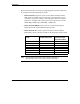
Specifications 5.1.2 BreezeACCESS XL Frequency Model Uplink Band (GHz) Uplink-Downlink Separation (MHz) BreezeACCESS 3.5a 3.410-3.452 100 BreezeACCESS 3.5a1 3.400-3.450 100 BreezeACCESS 3.5b 3.450-3.500 100 BreezeACCESS 3.5e 3.425-3.450 50 BreezeACCESS 2.6b 2.551-2.593 74 BreezeACCESS 3.3 3.300-3.324 76 BreezeACCESS 3.8 3.925-4.
Specifications 5.1.3 BreezeACCESS MMDS Frequency 2.500GHz –2.686GHz Radio Access Method FH-CDMA or TDMA Operation Mode Time Division Duplex Channel Bandwidth 2 MHz Output Power (at antenna port) 29 dBm typical. Power Control range – 20 dB Sensitivity 1Mbps -93 2Mbps -86 3Mbps -78 -6 (dBm at antenna port, BER 1E10 ) Data Rate 3Mbps max Modulation Multilevel GFSK 5.
Specifications 5.4 Interfaces Interface Outdoor Unit RF (AU-E) N-Type jack lightning protected IF TNC jack, lightning protected Indoor Equipment TNC jack, lightning protected Ethernet 10BaseT (RJ-45) with two embedded LEDs Monitor 3-pin low profile Power 12 VDC via the IF cable 4-pin power connector (BS-PS) DC plug for the AU-PS power supply (AU-NI) 5.
Specifications 5.7 Environmental Outdoor Unit 0 Indoor Equipment 0 0 0 Operating Temperature -40 C to 60 C 0 C to 45 C Operating Humidity 5%-95% non-condensing Weather protected 5%-95% non condensing 5.8 Standards Compliance, General Type Unit Standard EMC BreezeACCESS II FCC Part 15.247, EN 300 826 (LP models) BreezeACCESS MMDS FCC Part 15.
Appendix A. Using Telnet APPENDIX A. USING TELNET Use the following procedure to connect to BreezeACCESS units via a Telnet session. 1. Connect the PC to the Ethernet port of the unit (or the hub to which the unit is connected) using a straight Ethernet cable. If you connect the PC directly to a unit that is normally connected to a hub, use a crossed Ethernet cable. You may also connect the PC to any Ethernet port on the network and communicate with the unit to be managed via the wired or wireless media.
Appendix A. Using Telnet 5. In the Host Name field, enter the IP address of the unit to be managed. 6. Set the Port field to Telnet (this is the default). 7. Set the Terminal Type to VT100 (this is the default). If the VT100 option in not available, do the following. Select Terminal-Preferences from the Telnet window menu and click the VT-100/ANSI radio button (as shown below). 8. Click in the Connect dialog box. The Select Access Level of the Monitor program should be displayed. 9.
Appendix B. Basic Parameters APPENDIX B. BASIC PARAMETERS The following parameters are relevant to all BreezeACCESS products. • IP Address – Displays the current IP address of the unit and allows entry of a new IP address (4 x 3 digit octets, separated by dots). The default IP Address is 010.000.000.001. • Subnet Mask – Displays the current subnet mask of the unit and allows entry of a new subnet mask (4 x 3 digit octets, separated by dots). The default mask is 255.000.000.000.
Appendix B. Basic Parameters ∗ Automatic – Search for a DHCP Server for configuration of the IP parameters. If a DHCP Server is not found within approximately 40 seconds, use the currently configured IP parameters. The default is Disable. ⇒ Access to DHCP - To define the port through which the unit is allowed to communicate with a DHCP server. The options are the following: ∗ From Wlan Only ∗ From Ethernet Only ∗ From Both Ethernet & Wlan The default for an Access Unit is From Ethernet Only.
Appendix B. Basic Parameters • Hopping Set – Displays the selected hopping set. Each hopping standard has 3 hopping sets. The hopping set selected in this screen determines which hopping sequences are available in the Hopping Sequence screen. Always use the same hopping set per site (with different hopping sequences) to minimize the possibility of collisions on the wireless media. The default value is 1. This parameter is set only in the AU.
Appendix B. Basic Parameters Table 5-1. Country Standards Supported by BreezeACCESS II Hopping Sync Support 60 Hopping Sequences per Hopping Set 20 2450 to 2483.5 30 10 No Europe ETSI 2400 to 2483.5 79 26 Yes France 2446 to 2483.5 35 11 Yes Israel 2418 to 2457 35 11 Yes Korea 2427 to 2454 23 4 Yes Japan 23 or 79 15 4 or 26 5 Yes Netherlands 2470 to 2497 or 2400 to 2483.5 2452 to 2470 Spain 2447 to 2473 27 9 Yes US FCC 2400 to 2483.5 79 26 No Mexico 2450 to 2483.
Appendix B. Basic Parameters Parameters Specific for BreezeACCESS MMDS The following parameters are set in BreezeACCESS MMDS products. • Hopping Shift –Displays the current value of the hopping shift parameter and allows entry of a new hopping shift value. This parameter is available only in Access Units – the Subscriber Units learn it during the association process.
Appendix B. Basic Parameters ⇒ Add Frequencies – Allows adding discrete hopping frequencies or frequency ranges. Enter a list of frequencies and/or frequency ranges to be added, e.g. 2501.500,2407.500-2519.500, 2525.500.Use a comma to separate between entries (no spaces). The allowed entries are from 2500 to 2688 in steps of 0.5MHz. The frequencies (either the start and stop frequencies of a range or discrete frequencies) can be in the following formats: MHz Resolution, e.g. 2520 kHz resolution, e.g. 2501.
Appendix B. Basic Parameters • ∗ An updated list of all the hopping frequencies to be used after the next Reset. ∗ The current sequence of operational hopping frequencies Hopping Sync (BS-AU only) – Displays the current Hopping Sync status of the unit and allows defining a new status. When several AUs that use the same frequencies and different Hopping Shifts are co-located, their operation should be synchronized in terms of Hopping Shift initialization and timing.
Appendix B. Basic Parameters • Frequency Offset – Displays the current offset of the Hopping Band from the beginning of the available frequency range, and allows entry of a new offset. The offset is measured in channels, where each channel is 2 MHz. For example, in products operating in the 3.5a band (3.410-3.452 GHz uplink), a Frequency Offset of 5 (10 MHz) will cause the hopping band to start at 3.420 GHz for the uplink and at 3.520 GHz for the downlink.
Appendix B. Basic Parameters • Flexible Hopping Definition– Allows defining the sub-bands to be used; displays the selected sub-bands, the hopping frequencies that will be used as a result of these selections and the current hopping sequence (based on the previous selections made before the last Reset). The new settings will go into effect only after the next Reset.
Appendix B. Basic Parameters ⇒ Channel Spacing Guard Band 1MHz 1MHz 1.75MHz 0.75MHz 2MHz 1MHz The available selections in products that support all the options are 1, 1.75 and 2MHz. In some products only a subset of these options may be available. The default is 2MHz. Note: Changing the value of the Channel Spacing will erase the current list of defined Sub-bands/frequencies ⇒ Define Sub-bands – Allows defining a new list of sub-bands and/or discrete frequencies.
Appendix B. Basic Parameters Use a comma to separate between entries. Use a hyphen to define subbands (no spaces). When a discrete frequency is defined, it is the actual hopping frequency to be used. When a sub-band is defined, the hopping frequencies are determined by the value of the Channel Spacing parameter (see Channel Spacing above). Note: Channel Spacing parameter should be configured prior to defining a new set of sub-bands.
Appendix B. Basic Parameters Note: • The hopping frequencies are calculated for each sub-band separately. Therefore, the hopping frequencies calculated for two consecutive sub-bands may differ from the hopping frequency calculated for a single “combined” band (e.g. the result for the entries 3410-3420,3420-3420 may differ from the results for the entry 3410-3430). Hopping Sync (Access Unit only) – Displays the current Hopping Sync status of the unit and allows defining a new status.
Appendix C. MMDS Channels and Frequencies APPENDIX C. MMDS CHANNELS AND FREQUENCIES Channel Name Frequency Band (MHz) Low Frequency (MHz) High Frequency (MHz) A1 2500 - 2506 2501.5 2504.5 B1 2506 - 2512 2507.5 2510.5 A2 2512 - 2518 2513.5 2516.5 B2 2518 - 2524 2519.5 2522.5 A3 2524 - 2530 2525.5 2528.5 B3 2530 - 2536 2531.5 2534.5 A4 2536 - 2542 2537.5 2540.5 B4 2542 - 2548 2543.5 2546.5 C1 2548 - 2554 2549.5 2552.5 D1 2554 - 2560 2555.5 2558.
Appendix C. MMDS Channels and Frequencies Channel Name Frequency Band (MHz) Low Frequency (MHz) High Frequency (MHz) D4 2590 - 2596 2591.5 2594.5 E1 2596 - 2602 2597.5 2600.5 F1 2602 - 2608 2603.5 2606.5 E2 2608 - 2614 2609.5 2612.5 F2 2614 - 2620 2615.5 2618.5 E3 2620 - 2626 2621.5 2624.5 F3 2626 - 2632 2627.5 2630.5 E4 2632 - 2638 2633.5 2636.5 F4 2638 - 2644 2639.5 2642.5 G1 2644 - 2650 2645.5 2648.5 H1 2650 - 2656 2651.5 2654.5 G2 2656 - 2662 2657.
Appendix D. FCC-Certified Antennas for BreezeACCESS II APPENDIX D. FCC-CERTIFIED ANTENNAS FOR BREEZEACCESS II Table D-1 lists the FCC-certified antennas that can be ordered from BreezeCOM. Table D-1. BreezeCOM FCC-Certified Antennas BreezeCOM Antenna Kit Note: BreezeACCESS Series Antenna Gain; H & V Coverage AN1079 17.
Appendix D. FCC-Certified Antennas for BreezeACCESS II Table D- 2. Required Adjustments Antenna Gain (dBi) Allowed RF Power in dBm (at antenna port) Required Attenuation from Maximum Power (dB) 24 12 14 18 18 8 17 19 7 16 20 6 13 23 3 <10 26 0 Use the Transmit Power Control parameter to change the gain of the Tx power circuits as required. A value of 15 represents the highest transmit power level. A lower value represents a lower transmit power level. The allowed range is from 0 to 15.
Appendix D. FCC-Certified Antennas for BreezeACCESS II Table D- 3. Transmit Power Control Values to Achieve Attenuation from Maximum Power RG 58 Cable Length (m) Value for 5 dB Attenuation Value for 10 dB Attenuation Value for 15 dB Attenuation 0-6 5 2 0 12 6 3 0 18 7 5 2 24 8 6 3 30 8 7 4 Use the factors in Table D- 4 to calculate the applicable values of the Transmit Power Control parameter for other cable types, as a function of the cable length.