Voice Gateways System Manual SW Version: SIP R2J July 2007 P/N: 214612
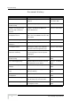
Document History Document History Topic Description Date Issued 1.2.8 Connectors The connectors' specifications were Version 1.0 updated. November, 2005 Commissioning description added. Version 1.0 November 2.4 Notes on Using the Voice Using the VG with BreezeMAX and Version 1.0 November Gateway (VG) in Alvarion's BreezeACCESS VL 2.3 Installation and Commissioning Systems 3.2 Accessing the Web Detailed instructions for accessing the Version 1.
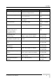
Legal Rights Topic Description Date Issued 3.7.6 Line Configuration Page The Line Configuration submenu was Version 1.1 February added to the Telephone menu 2006 The RTP Statistics submenu was added Version 1.1 February to the System menu 2006 Download option from an HTTP server Version 1.1 February was added. 2006 Logout option added. Version 1.1 February 3.9.5 RTP Stats Page 3.10 Upgrade Page 3.12 Logout Page 2006 General No H323 support Version 1.2 August 2006 2.
Legal Rights Legal Rights © Copyright 2007 Alvarion Ltd. All rights reserved. The material contained herein is proprietary, privileged, and confidential and owned by Alvarion or its third party licensors. No disclosure thereof shall be made to third parties without the express written permission of Alvarion Ltd. Alvarion Ltd. reserves the right to alter the equipment specifications and descriptions in this publication without prior notice.
Legal Rights invoice date (the "Warranty Period")". During the Warranty Period, Alvarion may release to its Customers firmware updates, which include additional performance improvements and/or bug fixes, upon availability (the "Warranty"). Bug fixes, temporary patches and/or workarounds may be supplied as Firmware updates. Additional hardware, if required, to install or use Firmware updates must be purchased by the Customer.
Legal Rights WARRANTIES OR CONDITIONS, EXPRESS OR IMPLIED, EITHER IN FACT OR BY OPERATION OF LAW, STATUTORY OR OTHERWISE, INCLUDING BUT NOT LIMITED TO WARRANTIES, TERMS OR CONDITIONS OF MERCHANTABILITY, FITNESS FOR A PARTICULAR PURPOSE, SATISFACTORY QUALITY, CORRESPONDENCE WITH DESCRIPTION, NON-INFRINGEMENT, AND ACCURACY OF INFORMATION GENERATED. ALL OF WHICH ARE EXPRESSLY DISCLAIMED. ALVARION' WARRANTIES HEREIN RUN ONLY TO PURCHASER, AND ARE NOT EXTENDED TO ANY THIRD PARTIES.
Legal Rights Important Notice This user manual is delivered subject to the following conditions and restrictions: This manual contains proprietary information belonging to Alvarion Ltd. Such information is supplied solely for the purpose of assisting properly authorized users of the respective Alvarion products.
About This Manual This manual describes Alvarion's Voice Gateway units and how to install, operate and manage them. Version R2J supports SIP only. This manual is intended for technicians responsible for installing, setting up and operating the Voice Gateway, and for system administrators responsible for managing the Voice Gateways. This manual contains the following chapters and appendices: Chapter 1 - System Description: Describes the Voice Gateway and its functionality.
Contents Chapter 1 - System Description 1.1 Introducing the Voice Gateway.................................................................................... 2 1.2 Specifications ................................................................................................................ 3 1.2.1 Telephony and Fax Services................................................................................ 3 1.2.2 Security ........................................................................................
Contents 2.4.1 BreezeMAX System (Version 1.5 and higher) ................................................... 14 2.4.2 BreezeACCESS VL System (Version 3.1) ......................................................... 14 Chapter 3 - Using the Web Configuration Server 3.1 Introduction to the Web Configuration Server ......................................................... 16 3.2 Accessing the Web Configuration Server................................................................. 17 3.
Contents 3.7.7 Dial Plan Schemes............................................................................................. 54 3.8 BW Reservation - DRAP Configuration Page ........................................................... 58 3.9 System Menu ............................................................................................................... 62 3.9.1 Set Security Password Page.............................................................................. 62 3.9.2 Localization Page......
Contents Appendix C - New Features C.1 Metering Support......................................................................................................... 90 C.2 Sending VoIP Performance Data to a Remote System ............................................ 90 C.3 Customized Ring Signals ........................................................................................... 91 C.4 Spanning Tree Working Mode Configuration ........................................................... 91 C.
1 Chapter 1 - System Description In This Chapter: “Introducing the Voice Gateway” on page 1-2 “Specifications” on page 1-3
Chapter 1 - System Description 1.1 Introducing the Voice Gateway Alvarion's Voice Gateway enables operators and service providers using Alvarion's Broadband Wireless Access system to provide subscribers with a number of broadband services transparently. The Voice Gateway enables bundling services such as telephony (Voice over IP) and high speed Internet to end-users. IP-telephony services are supported for standard analog phones or G3 fax machines.
Specifications 1.2 Specifications 1.2.1 Telephony and Fax Services Table 1-1: Telephony and Fax Services Item Description VoIP Standard H323 model: H323v2/4 SIP model: SIP (RFC 3261) Internal Class 5 Services Call Waiting, 3-party call, call hold and call alteration, differentiated ringing tones (refer to Appendix A for more details) External Class 5 Services Activation/deactivation of class 5 services supported by the IP-telephony system Fax G3 compliant V.17 14.
Chapter 1 - System Description 1.2.3 Voice Quality Table 1-3: Voice Quality Item Description Voice Codecs G.711 Ulaw G.711 Alaw G.729ab IEEE 802.1p layer-2 prioritization Prioritization DiffServ layer-3 prioritization Adaptive jitter buffer General Echo cancellation Speech sampling rate: 10-60 ms Silence suppression with comfort noise 1.2.
Specifications Table 1-5: Bridge Functionality Item Description Unknown address Forwarding Forward Unknown Policy Bridge Aging Time 1.2.6 180 seconds Mechanical Table 1-6: Mechanical Specifications Item Details Dimensions (W x D x H) 17.6 x 11 x 2.8 cm Weight 230g 1.2.7 Electrical Table 1-7: Electrical Specifications Item Details Power Input 12 VDC from an external power supply, 100-240 VAC, 50-60 Hz, 2A max. Power Consumption 1.2.8 10.5 W max.
Chapter 1 - System Description Table 1-8: Connectors Connection Description WAN Type 10/100Base-TX (RJ-45) Ethernet Connection to SU-IDU/hub: Straight Cable Length 12 VDC 1.2.9 max 100 m. Standard DC power jack to external power supply Regulatory Standards Compliance Table 1-9: Standards Compliance Type Standard EMC Low Voltage Directive (LVD) 73/23/EEC Electromagnetic Compatibility Directive (EMC) 89/336/EEG Safety IEC 60950 CSA C22.2 No.
2 Chapter 2 - Installation In This Chapter: “Installation Requirements” on page 2-8 “Front and Rear Panel Components” on page 2-9 “Installation and Commissioning” on page 2-11 “Notes on Using the Voice Gateways in Alvarion's Systems” on page 2-14
Chapter 2 - Installation 2.1 Installation Requirements 2.1.1 Packing List Voice Gateway with one (VG-1D1V) or two (VG-1D2V) Phone Ports Power supply with a DC connecting cable Mains power cable 2.1.2 Additional Installation Requirements A straight Ethernet cable for connecting the WAN port to the SU-IDU An Ethernet cable for connecting to the user's data equipment (straight for connecting to a PC, crossed for connecting to a hub/switch) Standard phone cable(s) with RJ-11 connectors.
Front and Rear Panel Components 2.2 Front and Rear Panel Components 2.2.1 Connectors Figure 2-1: Voice Gateway VG-1D2V Back Panel NOTE The VG-1D1V has a single Phone connector.
Chapter 2 - Installation For more details on configuration of DHCP and static IP parameters, refer to Section 3.5.2. 2.2.3 LEDs Figure 2-2: VG-1D2V Front Panel NOTE The VG-1D1V has a single Phone LED.
Installation and Commissioning 2.3 Installation and Commissioning The unit can be placed on a desktop or a shelf. The location should be selected taking into account the necessary connections to mains power, SU-IDU and user's data/telephony equipment. It is assumed that installation and commissioning of the SU has already been completed and that the SU is connected to the Base Station.
Chapter 2 - Installation 6 If the Web Configuration Server is password protected, you will be prompted to enter your username and password in order to log in to the system. The default username is operator and the default password is installer. See Chapter 3 for details on using the Web Configuration Server. 7 Configure the necessary parameters according to instructions supplied by the system administrator.
Installation and Commissioning 13 Use standard telephone cord(s) with RJ-11 termination to connect the telephony equipment to the unit. 14 Verify proper operation using the LED indicators (see Table 2-2). 15 To verify data connectivity, from the end-user's PC or from a portable PC connected to the unit, try to connect to the Internet or to ping another unit in the network. 16 Verify proper telephony operation by establishing a call to another telephone (for each enabled line).
Chapter 2 - Installation 2.4 Notes on Using the Voice Gateways in Alvarion's Systems 2.4.1 BreezeMAX System (Version 1.5 and higher) Access the Monitor program of the SU from a PC connected to the LAN port of the Gateway. The SU's Monitor program uses the fixed IP address 192.168.254.251 with the subnet mask 255.255.255.0. The PC used for accessing the Monitor program should be configured to belong to the same subnet. It is recommended to set the PC's IP address to 192.168.254.
3 Chapter 3 - Using the Web Configuration Server In This Chapter: “Introduction to the Web Configuration Server” on page 3-16 “Accessing the Web Configuration Server” on page 3-17 “Using the Web Configuration Server” on page 3-18 “Home Menu - Product Info Page” on page 3-20 “WAN Menu” on page 3-22 “VLAN Tagging Menu” on page 3-26 “Telephone Menu” on page 3-38 “BW Reservation - DRAP Configuration Page” on page 3-58 “System Menu” on page 3-62 “Upgrade Page” on page 3-68 “Restart Page” on
Chapter 3 - Using the Web Configuration Server 3.1 Introduction to the Web Configuration Server The Voice Gateway can be configured using the following methods: The Web Configuration Server An .ini-file loaded into the unit from a TFTP-server or automatically downloaded using DHCP option 43. This document describes the configuration using the Web Configuration Server.
Accessing the Web Configuration Server 3.2 Accessing the Web Configuration Server To manage the unit you must have prior knowledge of its WAN IP Address. Follow the steps below to access the Web Configuration Server: 1 Open a web browser. 2 Enter the WAN IP address of the unit in the Address field of the browser and click Enter. E.g., http://192.168.254.254 (default).
Chapter 3 - Using the Web Configuration Server 3.3 Using the Web Configuration Server The Web Configuration Server view consists of a number of menu links (to the left). Clicking on each of them will display the configuration/status page for the selected menu item, with the applicable content (configurable parameters/options or status information) in the main area. Several pages include a page selection bar at the top of the page, enabling selection between several pages related to the same menu item.
Using the Web Configuration Server CAUTION There is no control that the entered values are valid or have the correct format or range. If invalid values are entered, access to the unit may be lost and in that case a factory default procedure must be performed. Refer to Section 2.2.2 for information about how to reset the Voice Gateway to factory default parameters.
Chapter 3 - Using the Web Configuration Server 3.4 Home Menu - Product Info Page The Product info page provides general information on the Voice Gateway.
Home Menu - Product Info Page Table 3-1: Product Info Page Parameters Parameter Description Reported download status The status of the SW download operation. For more details refer to Section 3.10.1. Main software revision The unit's main SW version Operator defaults revision The custom .ini file (if exists) In any case of contact with Alvarion Customer Service, include the Default configuration, Downloader revision, Main software revision and Operator defaults revision (.ini file) if exists.
Chapter 3 - Using the Web Configuration Server 3.5 WAN Menu The WAN menu page includes settings related to the operation and functionality on the WAN (network) side of the unit. NOTE Be careful when setting these parameters to avoid conflicts in the network. The WAN page selection bar includes the following options: WAN Status (Section 3.5.1) WAN Configuration (Section 3.5.2) 3.5.
WAN Menu Table 3-2: WAN Status Page Parameters Parameter Description Interface Status Enabled The administrative status of the WAN port: Yes or No. In the current version the administrative status cannot be disabled. Service The configured operation mode. In current version it is always Bridged. Bridge Status The method of handling packets with an unknown destination address. In the current version it is always Forwarding.
Chapter 3 - Using the Web Configuration Server 3.5.2 WAN Configuration Page Figure 3-4: WAN Configuration Page The WAN Configuration page includes the following components: Table 3-3: WAN Configuration Page Parameters Parameter Description Device Operating Mode The operating mode of the unit. In current version the operation mode is always Bridge. Obtain WAN configuration using Select this option to obtain IP parameters from a DHCP server. DHCP See also Section 2.2.2.
WAN Menu Table 3-3: WAN Configuration Page Parameters Parameter Description Client identity Applicable only if the "Obtain WAN configuration dynamically" option is selected. The method used for identifying the client (Option 61). The options are: Standard: The unit's MAC address Custom: An identification string of up to 25 characters. The default is null (an empty string) Vendor ID Applicable only if the "Obtain WAN configuration dynamically" option is selected. The Vendor ID (Option 60).
Chapter 3 - Using the Web Configuration Server 3.6 VLAN Tagging Menu The VLAN Tagging page selection bar includes the following options: VLAN Tagging (Section 3.6.1) VoIP VLAN Configuration (Section 3.6.3) 3.6.1 VLAN Tagging Page The Voice Gateway supports 802.1Q VLAN standard, allowing IEEE 802 Local Area Networks (LANs) of all types to be connected together with Media Access Control (MAC) Bridges, as specified in ISO/IEC 15802-3.
VLAN Tagging Menu The VLAN page enables defining up to 16 VLANs, and it includes the following components: Table 3-4: VLAN Page Parameters Parameter Description Tagged Port Membership A table displaying the defined VLANs. For details on modifying the table refer to Section 3.6.2 below. Untagged VLAN ID The VLAN ID that is defined for untagged data on the WAN port (text box on the left side) and the LAN port (text box on the right side).
Chapter 3 - Using the Web Configuration Server Figure 3-6: VLAN Editor (Add VLAN) 2 Enter the VLAN ID (1 to 4094), VLAN NAME (A descriptive string of printable characters. Do not use special characters such as space or comma), and the VLAN priority tag (0 to 7). 3 If applicable packets need to be tagged on the WAN/LAN port, check the relevant Yes option. Otherwise check the No option. Note that only one VLAN can be untagged on each port (or on both). 4 Click OK.
VLAN Tagging Menu Figure 3-7: VLAN Editor (Delete VLAN) 2 Click on the Delete button. The entry will be removed from the Tagged Port Membership table. 3.6.
Chapter 3 - Using the Web Configuration Server The VoIP VLAN configuration page enables defining the following parameters: Table 3-5: VoIP VLAN Configuration Page Parameters Parameter Description Call Signaling VLAN Tag The VLAN ID tag for VoIP call signaling packets. If not set, the Default VLAN ID set for WAN (in the VLAN Tagging page) will also apply for VOIP. Priority Tag The Priority tag for VoIP call signaling packets.
VLAN Tagging Menu VLAN200 (Data) Untagged VLAN100 (Voice & Management) POTS Figure 3-9: VLAN Configuration Example 1 1 In the VLAN page, click Add VLAN to open the VLAN Editor. 2 In the VLAN Editor, enter the follwing for Voice and Management VLAN: VLAN ID: 100 VLAN NAME: Voice&Mng VLAN Priority: 5 WAN: Yes LAN: No 3 Click OK to add the VLAN to the Tagged Port Membership table. 4 Enter the VLAN ID for Voice and Management (100) in the field Default VLAN ID on WAN port, and click Save.
Chapter 3 - Using the Web Configuration Server 7 In the VLAN Editor, enter the follwing for data: VLAN ID: 200 (an arbitrary selection-a VLAN ID is required for defining the untagged data. This VLAN tag is only used internally in the unit) VLAN NAME: Data VLAN Priority: 0 WAN: Yes LAN: No 8 Click OK to add the VLAN to the Tagged Port Membership table. 9 Enter the VLAN ID for untagged data (200) in the fields Untagged VLAN ID on LAN port and click Save.
VLAN Tagging Menu VLAN 200 VLAN100 VG-1 POTS VG-2 Untagged Figure 3-10: VLAN Configuration Example 2 3.6.5.1 VG-1 Configuration 1 In the VLAN page, click Add VLAN to open the VLAN Editor. 2 In the VLAN Editor, enter the follwing for Voice and Management VLAN: VLAN ID: 100 VLAN NAME: Voice&Mng VLAN Priority: 7 WAN: Yes LAN: Yes 3 Click OK to add the VLAN to the Tagged Port Membership table.
Chapter 3 - Using the Web Configuration Server Signaling and RTP. Enter 7 in the Priority Tag field for both Call Signaling and RTP. Click Save VoIP VLAN Settings. Go back to the VLAN Tagging page. 6 In the VLAN page, click Add VLAN to open the VLAN Editor. 7 In the VLAN Editor, enter the follwing for Data VLAN: VLAN ID: 200 VLAN NAME: Data VLAN Priority: 4 WAN: Yes LAN: Yes 8 Click OK to add the VLAN to the Tagged Port Membership table.
VLAN Tagging Menu VLAN ID: 300 (an arbitrary selection-a VLAN ID is required for defining the untagged data. This VLAN tag is only used internally in the unit) VLAN NAME: Untagged VLAN Priority: 0 WAN: Yes LAN: Yes 8 Click OK to add the VLAN to the Tagged Port Membership table. 9 Enter the VLAN ID for untagged data (300) in the fields Untagged VLAN ID on LAN port and Untagged VLAN ID on WAN port, and click Save. 10 Restart the unit to apply the changes. 3.6.
Chapter 3 - Using the Web Configuration Server 3.6.6.1 Method 1 1 In the VLAN page, click Add VLAN to open the VLAN Editor. 2 In the VLAN Editor, enter the follwing for Voice and Management VLAN: VLAN ID: 60 VLAN NAME: Voice&Mng VLAN Priority: 6 WAN: Yes LAN: No 3 Click OK to add the VLAN to the Tagged Port Membership table. 4 Enter the VLAN ID for Voice and Management (60) in the field Default VLAN ID on WAN port, and click Save.
VLAN Tagging Menu VLAN ID: 60 VLAN NAME: Voice&Mng VLAN Priority: 6 WAN: Yes LAN: No 3 Click OK to add the VLAN to the Tagged Port Membership table. 4 Enter the VLAN ID for Voice and Management (60) in the field Default VLAN ID on WAN port, and click Save. 5 In the Page Selection bar, click on VoIP VLAN Configuration to open the VoIP VLAN Configuration page. Enter 60 in the VLAN Tag fields for both Call Signaling and RTP. Enter 6 in the Priority Tag field for both Call Signaling and RTP.
Chapter 3 - Using the Web Configuration Server 3.7 Telephone Menu In the SIP model, the Telephone page selection bar includes the following options: SIP (Section 3.7.1) SIP Extensions (Section 3.7.2) NAT (Section 3.7.3) STUN Client (Section 3.7.4) ToS (Section 3.7.5) In the H323 model, the Telephone page selection bar includes the following options: H323 (Section 3.7.1) ToS (Section 3.7.
Telephone Menu 3.7.
Chapter 3 - Using the Web Configuration Server H323 Telephone page: Figure 3-13: H323 Telephone Page (VG-1D2V) The SIP Configuration page/H323 Telephone pages include the following components: 40 Operation
Telephone Menu Table 3-6: SIP Configuration/H323 Telephone Page Parameters Parameter Description Dialplan The Dialplan parameter defines how the Voice Gateway decides that a complete number has been dialed. See more details in Section 3.7.7. The default value is xx.T|xx.#, which means that each of the following schemes can be used: xx.T: Dial timeout. Any number of digits may be dialed.
Chapter 3 - Using the Web Configuration Server Table 3-6: SIP Configuration/H323 Telephone Page Parameters Parameter Description HA mode The High Availability mode defines the support of a secondary Gate Keeper/SIP Server for high system availability, redundancy, and scalability. When a secondary server is available, the unit will try to register to the secondary server after 10 failed attempts to register to the primary server.
Telephone Menu Table 3-6: SIP Configuration/H323 Telephone Page Parameters Parameter Description User Name The SIP user Name. Format (name or number) depends on the SIP (SIP model only) Password (SIP model only) H323 Alias server. A string of up to 25 characters. The SIP user Password. Format (name or number) depends on the SIP server. A string of up to 25 characters. The unit's name used when registering the unit at the Gate Keeper.
Chapter 3 - Using the Web Configuration Server Table 3-6: SIP Configuration/H323 Telephone Page Parameters Parameter Description Incoming CLIP The Calling Line Identity Presentation (Caller ID) option for the telephone line. If On is selected, the Caller ID information of a calling party in incoming calls will be displayed on a caller ID display attached to the telephone line. Caller ID can be restricted permanently using a customized .ini file. The default is Off.
Telephone Menu 3.7.1.1 Codecs and Fax Configuration After clicking the Set Codecs/Fax button, the Codecs and Fax Configuration page is displayed.
Chapter 3 - Using the Web Configuration Server The jitter buffer options are common to both lines (if applicable): Table 3-7: Jitter Buffer Options Parameter Description Adaptive Jitter Buffer Maximum The Voice Gateway uses a Jitter Buffer to eliminate jitter Delay effects. The size of the buffer changes dynamically to reflect actual jitter conditions.
Telephone Menu Table 3-8: Codecs and Fax Configuration Parameters Parameter Description SS The SS (Silent Suppression) option for outgoing calls. When the SS option is enabled, silence intervals are identified and only relevant information is transmitted, using less bandwidth than during voice activity intervals. This allows for a better overall utilization of the available bandwidth. It is possible to enable Silent Suppression with G729 codec.
Chapter 3 - Using the Web Configuration Server Table 3-8: Codecs and Fax Configuration Parameters Parameter Description T38 Fax The T38 check box indicates for each line whether to support the T38 Fax protocol. The default is checked (T38 Fax supported). Click on the Save button before leaving the page to save the new settings. The new settings will be applied after restarting the unit. 3.7.
Telephone Menu Table 3-9: SIP Extensions Page Parameters Parameter Description Encode SIP URI with User=Phone will be inserted in the Contact field of SIP uniform resource user parameters identifier (URI). Encode default port in Include default port in SIP uniform resource identifier (URI) even though it SIP URI is not mandatory according to standard.
Chapter 3 - Using the Web Configuration Server Click on the Save SIP Extensions Settings button before leaving the page to save the new settings. The new settings will be applied after restarting the unit. 3.7.3 NAT Traversal Configuration Page (SIP Only) NAT Traversal function can be used to allow the Voice Gateway to register to a SIP proxy server even though the Voice Gateway is connected behind a NAT device.
Telephone Menu Table 3-10: NAT Traversal Configuration Page Parameters Parameter Description Static NAT Mode: The NAT mode: On = Enable NAT Traversal function using manual setting. Auto = Enter NAT mode if any of the following conditions is met:a. IP-address = Private IP address b. "received" parameter in INVITE or REGISTER IP-address is not equal to internal IP address. Off = NAT Traversal function is disabled.The default is Off.
Chapter 3 - Using the Web Configuration Server Figure 3-17: STUN Client Configuration Page The STUN Client page includes the following components: Table 3-11: STUN Client Configuration Page Parameters Parameter Description STUN Client Mode Switch the STUN Client mode on or off. When on, turn off the Static NAT Traversal mode. STUN Server Address (IP or Domain) The IP address or Domain of the STUN server. STUN Server Port The port used by the STUN Server. The default is port 3478.
Telephone Menu Figure 3-18: ToS Page The ToS page includes the following components: Table 3-12: ToS Page Parameters Parameter Description Call signaling Packets ToS marking for call signaling packets. Enter a number in the range 0 to 255 (The first 6 bits is the value of the DSCP field) or null. The default is 0. RTP Packets ToS marking for RTP and RTCP packets. Enter a number in the range 0 to 255 (The first 6 bits is the value of the DSCP field) or null. The default is 0.
Chapter 3 - Using the Web Configuration Server Figure 3-19: Line Configuration Page Click on the Save button before leaving the page to save the new settings. The new settings will be applied after restarting the unit. The default is Sweden. 3.7.7 Dial Plan Schemes A dialplan gives the unit a map to determine when a complete number has been entered and should be passed to the gatekeeper/SIP server for resolution into an IP address.
Telephone Menu StringList::= String | String "|" StringList DialPlan::= String | "(" StringList ")" [0-9] denotes a single digit between 0 and 9. To configure a range of more than 10 numbers (e.g., 800xxx-819xxx) use the scheme: 80xxxx|81[0-9]xxx. A dialplan, according to this syntax, is defined either by a (case insensitive) string or by a list of strings. Regardless of the above syntax a timer is only allowed if it appears in the last position in a string (12T3 is not valid).
Chapter 3 - Using the Web Configuration Server Using supplemental external services (Example 3): When a soft switch or a SIP server/gatekeeper exists in the network and the user would like to use class 5 services which are not internal to the Voice Gateway e.g., *xy#, *xy*abcd#, #xy#, etc., the VG dialplan should be configured as follows: [*#][0-9*][0-9*].
Telephone Menu In ethereal trace, the "To" field in SIP INVITE is "1860123" For incoming calls VG can remove a prefix in the dialplan and show the number without the prefix on the phone display. Use the following notation: "<'replacement string':'received-string'>" For example: Set the dialplan to "<8:1860>xxx" When a number with the 1860 prefix is received (e.g., "1860123"), the prefix 1860 is replaced with the digit 8 and the number displayed is 8123.
Chapter 3 - Using the Web Configuration Server 3.8 BW Reservation - DRAP Configuration Page The Voice Gateway uses DRAP (Dynamic Resource Allocation Protocol) for efficient management of bandwidth resources for telephone calls.
BW Reservation - DRAP Configuration Page Table 3-13: DRAP Configuration Page Parameters Parameter Description Enable DRAP The Enable DRAP option defines whether DRAP is used for establishing telephone (voice and fax) calls. If enabled, a DRAP Server must be available to provision telephone calls. The default is disabled (unchecked).
Chapter 3 - Using the Web Configuration Server Table 3-13: DRAP Configuration Page Parameters Parameter Description Acknowledge Time The Acknowledge Time is the timeout out to be used between allocation requests. If no confirmation is received within this time, a new allocation request should be sent. The range is 1 to 10 (x 100 milliseconds). The default is 3 (300 milliseconds).
BW Reservation - DRAP Configuration Page Table 3-13: DRAP Configuration Page Parameters Parameter Description Vocoder Type The Vocoder Type parameter defines the codec to be used until an actual call is established. It is recommended to set a value that supports the worst-case scenario, e.g. the codec with the highest bandwidth requirement. Typically G711 should be configured, except in networks where only G729 is used.
Chapter 3 - Using the Web Configuration Server 3.9 System Menu The System page selection bar includes the following options: Security (Section 3.9.1) Localization (Section 3.9.2) SNMP (Section 3.9.3) Service Access (Section 3.9.4) RTP Stats (Section 3.9.5) 3.9.
System Menu Table 3-14: Set Security Password Page Parameters Parameter Description User name Enter the user name. The user name for users with operator privileges (full access and read/write privileges) is operator and for user with administrator privileges (partial access and read/write privileges) is admin. These user names cannot be changed. Old password A password used previously. The default password for users with operator privileges is installer.
Chapter 3 - Using the Web Configuration Server 3.9.2 Localization Page Figure 3-22: Localization Page The Localization page includes the following components: Table 3-15: Localization Page Parameters Parameter Description NTP Server The IP address of the NTP-server (optional). If an IP address is configured the NTP server usage is activated. The feature must be activated to support FSK-based caller ID. The default is disabled (no IP address). Time Zone The appropriate time zone.
System Menu 3.9.3 SNMP Configuration Page Figure 3-23: SNMP Configuration Page The SNMP Configuration page includes the following components: Table 3-16: SNMP Configuration Page Parameters Parameter Description SNMP Trap Configuration Trap Destination 1 to Trap Specify up to 6 IP addresses to which SNMP traps should be sent. destination 6 Only these stations will be able to manage the Voice Gateway.
Chapter 3 - Using the Web Configuration Server Table 3-16: SNMP Configuration Page Parameters Parameter Description Read Community The read community string, up to 20 printable characters, case sensitive. Default string is public. Write Community The write community string, up to 20 printable characters, case sensitive. Default string is private Click on the Save SNMP Settings button before leaving the page to save the new settings. The new settings will be applied after restarting the unit. 3.9.
System Menu 3.9.5 RTP Statistics Page The RTP Stats page enables to monitor from remote the performance of the last call. The displayed information includes: Bandwidth (kb/s), jitter, packet loss, and latency. NOTE The bandwidth relates to the payload only.
Chapter 3 - Using the Web Configuration Server 3.10 Upgrade Page The Upgrade page enables to control the process of downloading either a software file (with the extension .ro) or a configuration file (with the extension .ini) from a TFTP-server or from an HTTP server. Figure 3-26: Upgrade Page The Upgrade page includes the following components: Table 3-17: Upgrade Page Parameters Parameter Description Upgrade Type Auto The Voice Gateway will automatically select the server type for download.
Upgrade Page file is done automatically, including a restart of the unit. When the installation is complete and the unit has restarted, the Home Product Info page will be displayed (if not, click on the Refresh button). The version R2H implementation of the dialplan module is fully compliant with RFC3435. However, some previously acceptable dialplans are inconsistent with RFC3435 operation and must therefore be changed to ensure continued operation consistent with previous releases.
Chapter 3 - Using the Web Configuration Server bit-4 (0x10): TFTP session failed bit-5 (0x20): CRC error in downloaded image bit-6 (0x40): incompatible image 3.10.1.
Restart Page 3.11 Restart Page When settings have been inserted or altered, the Voice Gateway must be restarted in order to apply the new settings. Figure 3-27: Restart Page Click the Restart button to restart the Voice Gateway.
Chapter 3 - Using the Web Configuration Server 3.12 Logout Page Use this page to log out the system.
Parameters Summary 3.
Chapter 3 - Using the Web Configuration Server Table 3-18: Parameters Summary Parameter Range/Options Default Dialplan A string of up to 100 xx.T|xx.# characters. For details on format see Section 3.7.
Parameters Summary Table 3-18: Parameters Summary Parameter Range/Options Default H323 Alias A string of up to 25 characters Null A string of up to 25 characters Null 1030-65535 Line 1: 5060 (H323 model only) Telephone domain name (SIP model only) Port (SIP model only) Line 2: 5061 Message Waiting Account Null (SIP model only) Incoming CLIP On/Off Off Keepalive timeout 10-65535 seconds 1200 seconds Ring signal 0-9 0 Transport UDP/TCP UDP Adaptive Jitter Buffer 100-300 millisecond
Chapter 3 - Using the Web Configuration Server Table 3-18: Parameters Summary Parameter G711U Range/Options Default Select/Deselect Yes (checked)/No(unchecked) Yes (checked) SS Not applicable EC Enable/Disable Enabled Packet 10-150 milliseconds 20 ms Keypad SIP: None, RFC2833, None SIP INFO H323: H225, H245, RFC2833, None G729 Priority 1-3 2 Select/Deselect Yes (checked)/No(unchecked) Yes (checked) SS Enable/Disable Disabled EC Enable/Disable Enabled Packet 10-150 millisec
Parameters Summary Table 3-18: Parameters Summary Parameter Range/Options Default Use NOTIFY message to keep alive Yes (checked)/No 15 seconds the session with SIP proxy every X (unchecked) seconds 0-99999 seconds NAT Traversal Configuration Page (SIP model only) External NAT-mapped IP Address IP address Null Static NAT Mode On/Auto/Off Off STUN Client Mode On/Off Off STUN Server Address IP address/Domain Null STUN Server Port 1-65534 3478 Call signaling Packets 0-255 or null 0
Chapter 3 - Using the Web Configuration Server Table 3-18: Parameters Summary Parameter Range/Options Default Set security Password Page New password/ Confirm new Up to 20 printable characters, password case sensitive. A null (empty) string means no password. Localization Page NTP Server IP address or null for disable Null (NTP server disabled) NTP server Time Zone Drop Down Menu GMT+01:00 Adjust clock for daylight savings Yes/No Yes (checked) Trap Destination 1 to Trap IP addresses.
A Appendix A - Internal Class 5 Services In This Appendix: This appendix provides a description of the internal Class 5 services that are supported by the Voice Gateway.
Appendix A - Internal Class 5 Services A.
Using the Class 5 Services A.2 Using the Class 5 Services A.2.1 Call Waiting Description: One on-going call active, audible CW tone indicating new incoming call in progress. Table A-2: Call Waiting Service Action Event R0 Reject incoming call → Calling party hears busy tone. Continue with active call.0 R1 Disconnect on-going call and answer incoming call. R2 Place on-going call on hold, answer incoming call. A.2.
Appendix A - Internal Class 5 Services Table A-5: Call Drop Service Action Event R0 Disconnect call that is put on hold. Continue with on-going call. R1 Disconnect on-going call and return to call that is put on hold. A.2.5 3-Party Conference 1 Description: One on-going call active, place a new call to a third party and start conference.
Using the Class 5 Services Table A-8: Call Waiting Indication Tone Service Action Event *#43# Informs about present Call Waiting indication tone configuration: Three short beeps = off Two long beeps = on A.2.8 Call Forward Description: Available only when there are no calls active/in progress. Table A-9: Call Forward Service Action Event *21*# Enable Call Forward and do forward to . Indication tone is heard.
B Appendix B - Default Telephony Parameters In This Appendix: This appendix provides the default settings for various telephony parameters.
Appendix B - Default Telephony Parameters Table B-1: Default Telephony Parameters Parameter Definition Default Normal Ringing Signal The signal that end user will Cadence: 1 second on, 4 hear from the telephone set second off when a call is received Duration: 180 seconds Frequency: 25 Hz Ringing Tone The tone that sounds on the Cadence: 1 second on, 5 telephone set when ringing on second off the other side.
Table B-1: Default Telephony Parameters Parameter Definition Default Caller ID Standard The country standard and data Sweden, DTMF transmission method CID Alerting Method The method of alerting on the Polarity Reversal existence of CID data On-hook data transmission The timing for transmission of timing method CID data 2-Wire Impedance The impedance presented between the A and B wires of the telephone line in active state (nominal impedance).
C Appendix C - New Features In This Appendix: This appendix explains the new features and parameters configurable in the ini files. The ini files are generated and encrypted by Alvarion upon request. For a complete list of parameters refer to “SIP VG INI Parameters - Customer Questionnaire”.
Appendix C - New Features C.1 Metering Support The VG can generate metering pulses, reverse polarity and pulse metering. The metering pulse are generated in terms of the indication from head V5-Signal-Info in INFO message. The customer is required to select the pulse metering or the reverse polarity parameters. If pulse metering is selected, the frequency (12KHz or 16KHz), the pulse level duration and the interval parameters are also required. Default values are: Pulse Frequency: 12Khz.
Customized Ring Signals C.3 Customized Ring Signals The called VG can play customized ring signal specified in the Alert-Info header instead of playing local configured ring signal. The VG supports up to 10 different ring signal, that can be edited in the Ini file. C.
Glossary AS/NZS Australian and New Zealand Standard BW Band Width CLIP Calling Line Identification Presentation: A supplementary service used to show the number of a caller. CNI Calling Number Identification. CSA Canadian Standards Association CW Call Waiting DHCP Dynamic Host Configuration Protocol. A protocol for dynamically assigning IP addresses from a pre-defined list to nodes on a network.
Glossary EMC Electro-Magnetic Compatibility. The capability of equipment or systems to be used in their intended environment within designed efficiency levels without causing or receiving degradation due to unintentional EMI (Electro Magnetic Interference). EMC generally encompasses all of the electromagnetic disciplines. FCC Federal Communications Commission. A U.S. government agency that supervises, licenses, and controls electronic and electromagnetic transmission standards.
Glossary HTTP HyperText Transport Protocol: A protocol used to request and transmit files, especially web pages and web page components, over the Internet or other computer network. IDU Indoor Unit IEC International Electrotechnical Commission, Geneva, Switzerland, www.iec.ch: An organization that sets international electrical and electronics standards founded in 1906. It is made up of national committees from over 60 countries. IEEE Institute of Electrical and Electronics Engineers.
Glossary ISO International Organization for Standardization, Geneva, www.iso.ch: An organization that sets international standards, founded in 1946. The U.S. member body is ANSI. ISO deals with all fields except electrical and electronics, which is governed by the older International Electrotechnical Commission (IEC). With regard to information processing, ISO and IEC created JTC1, the Joint Technical Committee for information technology. ITU-T International Telecommunication Union Telecommunications.
Glossary MDI/MDIX MDI/MDIX is a type of Ethernet port connection using twisted pair cabling. The MDI (for Medium Dependent Interface) is the component that provides the physical and electrical connection to the cabling medium. An MDIX (for MDI crossover) is a version of MDI that enables connection between like devices. MDI ports connect to MDIX ports via straight-through twisted pair cabling; both MDI-to-MDI and MDIX-to-MDIX connections use crossover twisted pair cabling.
Glossary PPPoE Point-to-Point Protocol over Ethernet. PPPoE relies on two widely accepted standards: PPP and Ethernet. PPPoE is a specification for connecting the users on an Ethernet to the Internet through a common broadband medium, such as a single DSL line, wireless device or cable modem. All the users over the Ethernet share a common connection, so the Ethernet principles supporting multiple users in a LAN combines with the principles of PPP, which apply to serial connections.
Glossary SNMP Simple Network Management Protocol. A network management protocol that provides a means to monitor and control network devices, and to manage configurations, statistics collection, performance, and security. SNMP works by sending messages, called protocol data units (PDUs), to different parts of a network. SNMP-compliant devices, called agents, store data about themselves in Management Information Bases (MIBs) and return this data to the SNMP requesters.
Glossary URL Uniform Resource Locator, the global address of documents and other resources on the World Wide Web. The first part of the address indicates what protocol to use, and the second part specifies the IP address or the domain name where the resource is located. V.17 An ITU fax standard (1991) that uses TCM (Trellis-Coded Modulation, a technique for forward error correction) modulation at 12,000 and 14,400 bps for Group 3 faxes. It adds TCM to the V.
Glossary WAN Voice Gateways System Manual Wide Area Network. A computer network that spans a relatively large geographical area. Wide area networks can be made up of interconnected smaller networks spread throughout a building, a state, or the entire globe.