Eagle ProV3 UpgradeTilt & 360 Continuous Panning Instruction Manual Page 1 of 15
Contents 1. Features...............................................................................................................................................................3 2. Check List............................................................................................................................................................3 3. Equipment Required For Assembly....................................................................................................................4 4.
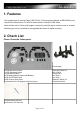
1. Features -This upgrade pack is used for Eagle F450-550 Pro V3 Camera Mount (Model: ALPRO3CMV3) only. -Improve the smoothness of Tilt and Pan axises with the new M0.5 POM Gears. -Allow the Pan axis to Panning 360 degree continuously with 360 degree continuous servo included. -Stabilize gyro mount is included on the upgraded fiber frame for easier mounting. 2. Check List Please Check the Follow parts.
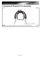
3.
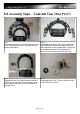
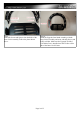
4.0 Assembly Steps – Uninstall Your Own ProV3 Step 1. Disassembly the Inner Circle Assembly from your ProV3 Camera Mount by moving 4pcs Alu Roll Bearing shaft 39mm. Step 2. Disassembly the whole Outer Frame Assembly and keep all the screws and metal rods for the later installation of the Upgrade Pack. Recognize the installation direction of each parts and frames. You may take a photo for later use. Step 3. Disassembly the Cam Stand Assembly and the Tilt Servo from the Inner Circle Assembly.
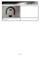
Step 5. Unstall the Bearing Mount Frames from the Inner Circle Assembly.
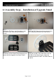
4.1 Assembly Steps – Installation of Upgrade Stand Step 1. Prepare the Tilt Servo, 1pcs Servo Horn, 1pcs M0.5 Servo Horn Gear and 4pcs M2x6mm Screws. Step 2. Install the M0.5 Servo Horn Gear onto the Servo Horn using 4pcs M2x6mm Hex Cap Screws. Step 3. Unistall the old Can Stand Frame Assemnly and replace with the Upgrade Cam Stand Frame. Step 4. Install the new M0.5 150T Main Gear onto the Side Rib of Cam Stand Frame. Follow the installation direction of M0.5 150T Main Gear on the photo.
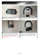
Step 5. Completed Upgraded Can Stand Assembly. Step 6. Prepare the Upgrade Bearing Mounts and the Inner Circle Assembly. Step 7. Install the Upgrade Bearing Mounts into the Inner Circle Assembly. Follow the orientation as shown on the photo. Distance A is larger than distance B. (Apply little amount of Thread Locker to the screws when installing metal parts.) Step 8.
Step 9. Insert M3 Screws and Spacers into both side of the Inner Circle Assembly. Follow the photo shown above. Step 10. Install the Upgrade Cam Stand Assembly with the Inner Circle Assembly and secur with M3 Screws and Self-Lock Nuts. Make sure the Upgrade Tilt M0.5 150T Main Gear is installed near the Tilt Servo Slot side of the Inner Circle Frame.
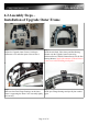
4.2 Assembly Steps – Installation of Upgrade Outer Frame Step 1. Prepare the Upgrade Outer Frames, 360 degree continuous servo and other parts as shown above. Step 2. Install the Alu Rods, fiber frames and Pan Bearing Mounts onto the Upgrade Outer Frame using M2x6mm Screws, and M2.5x8mm Screws for the Pan Bearing Mounts.(Apply little amount of Thread Locker to the screws when installing metal parts.) Step 3. Step 4.
Step 5. Installation of the Gyro Mounting Frame onto the Upgrae Outer Frames. Step 6. Insert the other side of Upgrade Outer Frame and secure it with M2X6mm Hex Cap Screws for Alu Rods and M2.5x8mm Screws for the Pan Bearing Mounts.(Apply little amount of Thread Locker to the screws when installing metal parts.) Step 7. Hole and compress two Alu Roll Bearing shafts with hand and tighten the shafts using M2x6 Hex Cap Screws .(This step will affect the smoothness and tolerance of the Roll Axis movement.
4.2 Assembly Steps – Servo Installation Step 1. Step 2. Install the Roll Servo onto the Upgrade Outer Frame Insert the Roll Servo gear onto the Roll Servo and using M2x6mm Hex Cap Screws and Nut.(Apply little secure it with M2 servo screw. amount of Thread Locker to the screws when installing metal parts.) Use a servo tester or receiver to set the servo onto the center position. Step 3. Step 4.
Step 5. Uninstall the Pan Gear Mount from the old assembly and install it with the M0.5 150T Main Gear using 4pcs M2x6mm Hex Cap Screws. Step 6. Insert the Upgrade Pan Main Gear into the Panning Mmain Shaft and install the 360 Degree Pan Servo onto the Outer Frame using 4pcs M2x10mm Screws with spacers. (Apply little amount of Thread Locker to the screws when installing metal parts.) Step7. Adjust whole 360 Degree Servo Assemnly to fit two upgrade M0.5 gears.
Step 9. Install the Tilt Servo With Alu Square Rod 30.5mm to the Inner Circle Frame using M2x6mm Hex Cap Screws. Make sure the direction of servo is correct. (Apply little amount of Thread Locker to the screws when installing metal parts.) Step 10. Install the servo horn with Upgrade Tilt Gear and adjust the tightness of the gears by adjusting the position of the Tilt Servo. Secure the servo and test with a Servo Tester or Receiver to ensure the movement angle of the Tilt Axis is fulfill your needs.
# Report any mistakes, please email to: info@alwarerc.com Related Video: http://www.youtube.