Senrigan-GP-45 Brushless Gimbal Instruction Manual v1.
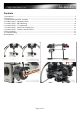
Contents 1. Introduction.........................................................................................................................................................3 2. Check List............................................................................................................................................................4 3. Equipment Required For Assembly....................................................................................................................5 4.
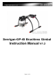
1. Introduction Introduction: Brushless Gimbal is the next generation technology for high quality aerial photography. Senrigan GP-45 Brushless Gimbal is driven directly with two Brushless Motors for two axis movement roll and tilt without gears or belts. The main advantages of this design compared to traditional actuators (servos) are the Brushless Gimbals have no backlash in the gear/belt, and it provides the instantaneous response to the disturbance.
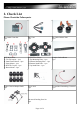
2. Check List Please Check the Follow parts.
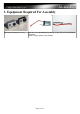
3. Equipment Required For Assembly 1pcs Gopro Camera (v1,2 or 3) 1pcs 3S 11.1V Lipo 800mAh (or above) or 1pcs JST to 3S Lipo Balance Connector. (Used to supply power to the Gimbal.
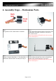
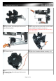
4. Assembly Steps – Mechanism Parts Step 1. Recognization of BL Gimbal Motor oriantation. Step 2. Install a Stand Frame Mount onto the Front Side of BL Gimbal Motor using M2.5x6mm Hex Cap Screws. This is the Tilt Axis. (Apply little amount of Thread Locker when securing screw to metal parts.) Step 3. Sep 4. Prepare 1x Bottom Stand Plate, 1x Top Stand Plate, 1x Install the Bottom Stand Plate with two Stand Frame Stand Frame Mount and the Assembly from Step 2. Mounts using 4x M2x6mm Hex Cap Screws.
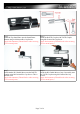
Step 5. Install the Top Stand Plate onto the Stand Frame Mounts using 4x M2x6mm Hex Cap Screws. (Apply little amount of Thread Locker when securing screw to metal parts.) Step 6. Install the Roll TR Coupler with Tilt TR Coupler using M2.5x6mm Hex Cap Screw. (Apply little amount of Thread Locker when securing screw to metal parts.) Step 7. Install another BL Gimbal Motor onto the Roll TR Coupler using M2.5x6mm Hex Cap Screws. This is the Roll Axis.
Step 9. Install the Coupler Carbon Boom with Spine Mount using M2x6mm Hex Cap Screw. (Apply little amount of Thread Locker when securing screw to metal parts.) Step 10. Insert two Boom Mounts onto the Coupler Carbon Boom. Step 11. Prepare the Assembly from step 10 and the Bottom Mounting Plate. Step 12. Install the Bottom Mounting Plate onto the Boom Mounts using M2.6x18mm Hex Cap Screws with M2.5 Self Lock Nuts.
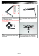
Step 13. Insert 8pcs Rubber Tension Damper Balls onto the Bottom Mounting Plate. Step 14. Install the Spine Mount onto the Roll Axis BL Gimbal Motor using M2.5x6mm Hex Cap Screws. (Apply little amount of Thread Locker when securing screw to metal parts.) Step 15. Close view of step 14. Step 16. Senrigan GP-45 Gimbal mechanism assembly view. Step 17. Insert 8pcs Rubber Tension Damper Balls onto the Top Mounting Plate.
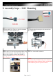
5. Assembly Steps – IMU Mounting Step 1. Prepare the IMU Unit. There is a specific orientation requirement to mount the IMU Unit. Step 2. Use a double-sided foam tape to stick onto the back side of IMU Unit. Step 3. Step 4. Stick the IMU Unit onto the Bottom Stand Plate using Close view for the IMU installation. double-sided foam tape. Check the double faced adhesive tape regularly to ensure that the IMU is securely positioned. (Ensure the orientation of the IMU is installed correctly.
Step 5. Arrange the cables of the Tilt BL Gimbal Motor and Roll BL Gimbal Motor with a zip tie.
6. Assembly Steps – CG Adjustment Step 1. Release the Top Stand Plate and prepare your own GoPro or cameras with similar weight. Use doublesided foam tape to secure the GoPro in the center of the Bottom Stand Plate. Step 2. Adjust the position of the Camera to the center axis of Tilt Motor. Step 3. Secure the GoPro by installing the Top Stand Plate back to the Stand Frame Mount using 4pcs M2x6mm Screws. (Apply little amount of Thread Locker when securing screw to metal parts.) Step 4.
7. Assembly Steps – Install with Landing Gear Step 1. Install the Advanced Landing Gear according to the above photo. (Apply little amount of Thread Locker when securing screw to metal parts.) Step 2. Mount the Gimbal Assembly onto the FPV Mount Plate using 4pcs M3x 10mm Hex Cap Screws with M3 Self-Lock Nuts. Step 3. Finished Gimbal Assembly with the Advanced Landing Gear. Step 4. Illustration to install with DJI F550 Hexacopter.
8. Assembly Steps – Gimbal Controller Board Step 1. Usage of different ports on the Gimbal Controller. (Best working power is 11.1V 3S Lipo.) Step 2. Insert the Tilt and Roll Controlling Connector into the Til and Roll Control Port on the Gimbal Controller. Step 3. Tilt Axis is controlled with 2-wire connector(Black=Ground, Red=Signal), and the Roll Axis is controlled with 1-wire connector. Connect these connectors into two free channels of your receiver.
Step 5. Secure the Gimbal Controller on the landing gear or on the bottom frame of your F450/ F550 Multicopter with tap Adhesive Tapes, Zip Tie or double-sided foam tape. Step 6. Bottom view of Gimbal Controller mounting on the landing gear. Connect the Tilt or Roll Axis Manual Control Connector to any free channels of your Receiver as to control the Tilt Axis manually. The Gimbal is recommended to power with 11.1V 3S Lipo Battery with JST connector.
9. Power On Steps Before Power On the Gimbal: 1. Please check the polarity on IMU cable making sure the vcc and gnd are connected to correct pins. 2. Make sure the IMU is facing down/ Upward for the new version when installing. Refer to IMU Mounting section. 3. We suggest to use 3s battery for GoPro or similar size cameras. 4. Double check the battery polarity before plugged in. 5. The Brushless Gimbal Controller is preset to plug-n-play with GoPro camera. There is no additional tuning needed.
10. Troubleshooting Q1: Why does the gimbal not stabilize the camera? A: Please check the battery voltage and if the LED is lit. Q2: Why is the gimbal not stabilizing the camera in right direction? A: Please refer to installation and make sure the IMU Unit is installed at right orientation and the motors are connected to right pins. Q3: Why is the gimbal shaking? A: Usually it is caused be wrong IMU facing, please make sure it is facing down. Refer to IMU Mounting section. Q4.