
Service manual


Always On UPS Systems
M0704_NX_Series_Service_Manual V2.17 2012-06-12 7
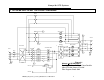
6. INVERTER
The inverter is composed of IGBT’s, inductors, capacitors, highly efficient filters, control
circuitry and protection circuitry. This inverter inverts the DC power received on the DC
bus to isolated, noise-free AC power, which is then supplied to the critical loads. Our
PWM wave generator is switching at a higher frequency well above the human audible
range.
The Voltage regulating circuitry limits the output voltage variation to within 1% of the
nominal voltage and special compensation circuitry has been added to eliminate output
distortion. Every component is oversized to accept a wide DC input range (from 285 to
420VDC), allowing the output waveform to remain sinusoidal throughout the entire
range. With the aid of dynamic feedback loop circuits the inverter maintains a true sine
wave output, even if non-linear loads are connected.
The system is designed and incorporates an independent inverter per phase. These
inverters are totally independent of each other preventing the possibility of cascading
failures while allowing the user to connect loads to adjacent inverters without affecting
the other inverters. This connectivity provides high-end voltage regulation under a 100%
unbalanced load situation.
The IGBT is operated in its optimal condition to obtain maximum efficiency, keeping
electrical costs to a minimum.
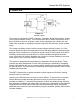
Usually, most UPS failures are a result of inverter failures. To prevent this occurrence,
Always On has included redundant protection circuitry to protect the inverter and
increase its reliability. To enhance this protection we have also added a high efficiency
filter designed to suppress the spikes and noise that can be reflected from the attached
loads back into the UPS system. Specifying oversized and high quality components,
additional semi-conductor fuses and allowing for good ventilation systems within further
increase reliability.
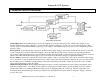
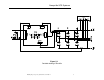
Figure 6.1
Inverter La
y
out