
Service manual


Always On UPS Systems
M0704_NX_Series_Service_Manual V2.17 2012-06-12 2
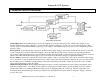
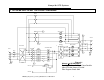
2. GENERAL BLOCK DIAGRAM
Normal Operation: The rectifier/charger converts the supplied AC power into DC (bus) power, which is then supplied to the
inverter and the battery charger. The DC to AC inverter then supplies continuous, noise free AC power to the critical loads. The
inverter output is synchronized with the bypass AC power source provided that the bypass AC power source is within the specified
frequency range.
Back-up Mode: As the batteries are connected to the DC bus they supply energy to the inverter via this DC bus, the AC power will
remain constant and continuous without interruption to the loads when the AC fails or falls out side of the operating parameters.
Upon return of the supplied AC input power the UPS the rectifier will automatically assume the DC load (charger, inverter) from the
batteries. The UPS will simultaneously supply power to the inverter and the battery charger to replenish the batteries.
Reserve Mode: If the inverter is placed into an abnormal condition, such as over temperature, short circuit, abnormal output voltage
or is overloaded for a period which exceeds the inverter’s limits, the inverter will automatically shutdown in order to protect itself. If
the AC utility power is within the normal parameters, the static switch will automatically transfer the load to the reserve (utility)
source without interruption of the AC output.
Maintenance Bypass Mode: During UPS maintenance procedures or battery replacement, the loads cannot be interrupted, and as
such the technician needs to turn off the inverter switch, close the bypass breaker and then open the rectifier and reserve (utility)
breakers. The UPS is now running in Maintenance By-pass mode supplying utility AC to the loads. The AC output will not be
interrupted during the manual bypass transfer procedure because the maintenance bypass switch is designed to supply continuous
power to the loads.
Figure 2.1
General Block Diagram