
User manual

10
Grounding the driver
Be sure to ground the protective
earth terminal (screw size: M4)
of the driver.
Tightening torque:
1.2 N·m (170 oz-in)
You can ground either of the
two protective earth terminals.
Protective earth
terminal
(Ground one of
these terminals.)
The terminal not grounded should be connected to the protective
earth lead of the motor cable.
Use a grounding wire (AWG16 to 14: 1.25 to 2.0 mm
2
), and do not
share the protective earth terminal with a welder or any other power
equipment.
When grounding the protective earth terminal, use a round terminal
and affix the grounding point near the driver.
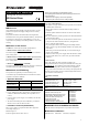
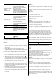
Connecting the 24 VDC power supply input,
regeneration resistor and electromagnetic
brake
Use the CN1 connector (6 pins) to connect the 24 VDC power
supply input, regeneration resistor thermal input and electromagnetic
brake. Connect the lead wire (AWG28 to 16: 0.08 to 1.25 mm
2
).
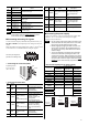
Display Description
24V+
24V−
24 VDC power supply input (Be sure to connect this pin
when an electromagnetic brake is used.)
TH1
TH2
Regeneration resistor thermal input (If this pin is not
used, short it using a jumper wire.)
MB1
Electromagnetic brake − (Connect the black lead wire of
the electromagnetic brake.)
MB2
Electromagnetic brake + (Connect the white lead wire of
the electromagnetic brake.)
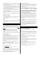
• Connecting method
Tightening torque:
0.4 N·m (56 oz-in)
Connector
screw size:
M2.5
• Connecting the 24 VDC power supply input
Connect a power supply of 24±10% VDC, 0.8 A or more.
Once a 24 VDC power supply is connected, you can check the
contents of alarms that have generated even when the main power is
cut off. If a motor with electromagnetic brake is used, be sure to
connect a 24 VDC power supply as the electromagnetic brake
power.
The 24 VDC power supply will not be used to drive the motor.
Connect a 24 VDC power supply as necessary.
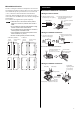
• Connecting the regeneration unit
• When the internal regeneration resistor is used
The driver has an internal regeneration resistor. The driver is shipped
with the TH1 and TH2 terminals of CN1, and RG2 and RG3
terminals of CN3, shorted respectively to enable the internal
regeneration resistor.
• When the optional regeneration unit (sold separately) is
used
Use the optional regeneration unit (sold separately) if gravitational
operation or other operation involving up/down movement, or
sudden starting/stopping of a large inertia load, will be repeated
frequently.
Regeneration
unit
AWG22
(AWG20 for RGB200)
To TH1 and TH2
terminals on CN1
To RG1 and RG2
terminals on CN3
AWG18
R
Note
• When connecting the regeneration unit, be sure to
remove the jumper wires from the CN1 connector and
CN3 connector.
• If the current consumption of the regeneration unit
exceeds the allowable level, the thermostat will be
triggered and a regeneration unit overheat alarm will
generate. If a regeneration unit overheat alarm
generates, turn off the power and check the content
of the error.
• Connecting the electromagnetic brake
Refer to “Connecting the motor”.
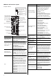
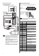
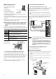
Connecting the battery
1. Hold the driver with its bottom facing up and plug the connector
attached at the end of the battery lead wires into the battery
connector.
2. Hook the tabs on the battery connector onto the mating parts on
the driver.
3. Push in the battery holder carefully by ensuring that the lead
wires are not pinched.
Lead wires with
connector
Battery holder
Hook
Step 1
Step 3
Step 2