
User manual


11
Note
• Installing or removing the battery must be performed
by qualified personnel with expert knowledge of the
handling of the driver and battery.
• Remove the battery if the driver is not turned on for
an extended period exceeding the data retention
period. Failure to do so may cause the battery fluid to
leak or battery performance to drop.
• When installing or removing the battery, cut off the
main power supply and 24 VDC power supply of the
driver.
• Once the battery is disconnected, the absolute motor
position stored in the driver will be lost. After the
battery has been installed, be sure to set the absolute
motor position again.
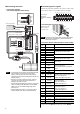
Connecting the data setter
Connect the cable of the data setter OPX-2A or cable supplied with
the data setting software MEXE02, to CN4 on the driver.
Data setter OPX-2A cable
or cable that comes with
the data setting software
MEXE02
Caution
The driver’s data edit connector (CN4) and
analog I/O signals connector (CN6) are not
insulated. When grounding the positive terminal
of the power supply, do not connect any
equipment (PC, etc.) whose negative terminal is
grounded. Doing so may cause the driver and
these equipment to short, damaging both.
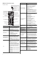
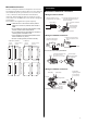
Setting
SW1
Internal potentiometers (VR1, VR2)
Mechanical rigidity setting switch (SW2)
Control mode setting switches (SW1-1, 1-2)
Absolute system setting switch (SW1-3)
Pulse input mode selector switch (SW1-4)
Note
The new setting of the absolute system setting switch
(SW1-3) and the pulse input mode selector switch
(SW1-4) will become effective after the power is cycled.
If a 24 VDC power supply is used, also cycle the 24
VDC power supply.
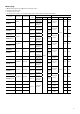
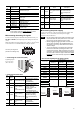
Control mode setting switches (SW1-1, 1-2)
These switches are used to set the control mode of the driver
(position control, speed control, torque control or tension control).
Position control
mode
Speed control
mode
Torque control
mode
Tension control
mode
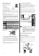
Absolute system (SW1-3)
Install the optional battery BAT01A (sold separately). When the
battery is connected, the current position will be retained even in the
event of power outage or after the driver power is cut off.
ON: Enable the absolute function
OFF: Disable the absolute function (factory setting)
The pulse input mode (SW1-4)
ON: 1-pulse input mode, negative logic
OFF: 2-pulse input mode, negative logic
Each mode can only be set with a negative logic using
the pulse input mode selector switch. To select a
positive logic, set the applicable parameter using the
OPX-2A or MEXE02.
Mechanical rigidity setting switch (SW2)
What is set with this switch varies depending on the control mode.
Control mode Description
Position control mode
Speed control mode
The switch sets the gain adjustment level
according to the mechanical rigidity.
Torque control mode Not used.
Tension control mode
The switch sets the minimum speed in the
simple mode. The switch is not used in high
function modeⅠor high function modeⅡ.
Internal potentiometers (VR1, VR2)
What is set with this switch varies depending on the control mode.
Control mode
Internal
potentiometers
Description
VR1
This switch sets the damping
control frequency.
Position control
mode
VR2 Not used.
VR1
This switch sets the speed
command value.
Speed control
mode
VR2
This switch sets the
acceleration/deceleration time.
VR1
This switch sets the torque
command value.
Torque control
mode
VR2 This switch sets the speed limit.
VR1
This switch sets the tension
command value.
Tension control
mode
VR2 This switch sets the speed limit.