
User manual

4
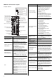
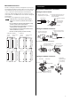
Names and functions of parts
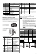
Example: NXD20-C
LED
SW1
Internal potentiometers
(VR1, VR2)
Mechanical rigidity
setting switch (SW2)
Analog I/O signals
connector (CN6)
Encoder connector (CN5)
Data edit connector (CN4)
Motor connector (CN2)
CHARGE LED
I/O signals connector
(CN7)
Battery connector (bottom)
Protective earth
terminal
Electromagnetic brake
terminal (CN1)
Regeneration register
thermal input terminal
(CN1)
24 VDC power supply
input terminal (CN1)
Regeneration resistor
terminal (CN3)
Power supply input
terminal (CN3)
Control mode setting
switches (SW1-1, 1-2)
Absolute system setting
switch (SW1-3)
Pulse input mode selector
switch (SW1-4)
Name Description
Control mode setting
switches (SW1-1, 1-2)
These switches are used to set the
control mode of the driver (position
control, speed control, torque control or
tension control).
Absolute system setting
switch (SW1-3)
This switch is effective in the position
control mode. Set the switch when the
absolute function of the driver is used by
connecting the optional battery BAT01A
(sold separately).
ON: Enable the absolute function.
OFF: Disable the absolute function.
The factory setting is “OFF.”
Pulse input mode
selector switch (SW1-4)
In the position control mode, this switch
toggles the driver between the 1-pulse
input mode and 2-pulse input mode
according to the pulse output mode of the
controller.
ON: 1-pulse input mode, negative logic.
OFF: 2-pulse input mode, negative logic.
LED
These LED indicate the status of the
driver.
POWER (green):This LED is lit while the
main power or 24 VDC is input.
ALARM (red):This LED will blink when an
alarm generates (a protective function is
triggered). You can check the generated
alarm (triggered protective function) by
counting the number of times the LED
blinks.
POS (green):This LED is lit in the position
control mode.
SPD (green):This LED is lit in the speed
control mode.
TRQ (green):This LED is lit in the torque
control mode.
TEN (green):This LED is lit in the tension
control mode.
Name Description
Mechanical rigidity
setting switch (SW2)
• Position control mode or speed control
mode
The switch sets the gain adjustment
level according to the mechanical
rigidity. The factory setting is “6.”
• Torque control mode
Not used.
• Tension control mode
The switch sets the minimum speed in
the simple mode. The factory setting is
“6.” The switch is not used in high
function modeⅠor high function mode
Ⅱ.
Internal potentiometers
(VR1, VR2)
• Position control mode
VR1: This switch sets the damping
control frequency.
VR2: Not used.
• Speed control mode
VR1: This switch sets the speed
command value.
VR2: This switch sets the
acceleration/deceleration time.
• Torque control mode
VR1: This switch sets the torque
command value.
VR2: This switch sets the speed limit.
• Tension control mode
VR1: This switch sets the tension
command value.
VR2: This switch sets the speed limit.
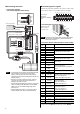
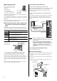
Data edit connector
(CN4)
Connect a PC in which the data setting
software MEXE02 has been installed, or
the data setter OPX-2A.
Encoder connector
(CN5)
Connect the motor encoder via a cable
for encoder.
Analog I/O signals
connector (CN6)
Connect the analog I/O signals.
I/O signals connector
(CN7)
Connect the I/O signals of the controller.
24 VDC power supply
input terminal
(CN1) [24V]
Connect 24 VDC. Once a 24 VDC power
supply is connected, you can check the
contents of alarms that have generated
even when the main power is cut off. If a
motor with an electromagnetic brake is
used, be sure to connect a 24 VDC power
supply for the electromagnetic brake
power.
Regeneration resistor
thermal input terminal
(CN1) [TH1, TH2]
Connect the optional regeneration unit
(sold separately). If no regeneration unit
is connected, plug in the CN1 connector
to short the TH1 and TH2 terminals.
Electromagnetic brake
terminal
(CN1) [MB1, MB2]
Connect the lead wires from the cable for
electromagnetic brake (24 VDC).
MB1: Electromagnetic brake − (black)
MB2: Electromagnetic brake + (white)
CHARGE LED (red)
This LED is lit while the main power is
input. After the main power has been
turned off, the LED will turn off once the
residual voltage in the driver drops to a
safe level.
Motor connector (CN2)
Connect the cable for motor or cable for
flexible motor to connect the motor.
Phase U: Red
Phase V: White
Phase W: Black