
User manual

6
• Before supplying power to the driver, turn all input signals to the
driver to OFF. Otherwise, the motor may start suddenly and cause
injury or damage to equipment.
• When moving the motor output shaft by hand while the motor is at
standstill, confirm first that the FREE input of the driver is turned
ON. If the FREE input is not ON, an attempt to move the motor
output shaft by hand may result in injury.
• Use a 24 VDC power supply that has been given reinforced
insulation between the primary side and secondary side. Failure to
do so may cause electric shock.
• Immediately when trouble has occurred, stop running and turn off
the driver power. Failure to do so may result in fire, electric shock
or injury.
• To prevent electric shock, use only an insulated screwdriver to
adjust the driver’s switches.
Maintenance and inspection
• To prevent the risk of electric shock, do not touch the terminals
while measuring the insulation resistance or conducting a
voltage-resistance test.
Disposal
• To dispose of the driver, disassemble it into parts and components
as much as possible and dispose of individual parts/components as
industrial waste.
Precautions for use
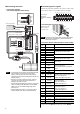
• Use the supplied cable to connect the motor and driver.
Always use the supplied cable to connect the motor and driver.
If a flexible cable or cable longer than 3 m (9.8 ft.) is to be used, an
appropriate cable must be purchased separately. Refer to the USER
MANUAL.
• Conduct the insulation resistance measurement or
withstand voltage test separately on the motor and the
driver.
Conducting the insulation resistance measurement or withstand
voltage test with the motor and driver connected may result in injury
or damage to equipment.
• Preventing leakage current
Stray capacitance exists between the driver’s current-carrying line
and other current-carrying lines, the earth and the motor,
respectively. A high-frequency current may leak out through such
capacitance, having a detrimental effect on the surrounding
equipment. The actual leakage current depends on the driver’s
switching frequency, the length of wiring between the driver and
motor, and so on.
When providing a leakage current breaker, use the following
products, for instance, which have high-frequency signal protection:
Mitsubishi Electric Corporation: NV series
Fuji Electric FA Components & Systems Co., Ltd.: EG and SG
series
• Preventing electrical noise
See the USER MANUAL
for measures with regard to noise.
• Saving data to the NV memory
Do not turn off the main power supply or 24 VDC power supply
while data is being written to the NV memory and 5 seconds after
the completion of data write. Doing so may abort the data write and
cause an EEPROM error alarm to generate.
The NV memory can be rewritten approx. 100,000 times.
• Motor excitation at power ON
When the driver has been set to lock the servo after the motor stops
in the position control mode or speed control mode: Turning on the
power supply will not excite the motor. To excite the motor, you
must turn the S-ON input ON.
You can set the motor to be excited automatically after the power
has been turned on, by changing the applicable driver parameter
using the data setter OPX-2A or the data setting software MEXE02.
• Use the optional regeneration unit (sold separately) if
gravitational operation or other operation involving up/down
movement, or sudden starting/stopping of a large inertial
load, will be repeated frequently.
The factory setting is to use the internal regeneration resistor. Note,
however, that the internal regeneration resistor does not support
continuous regenerative operation, gravitational operation or other
operations involving up/down movements, or frequent repeating of
sudden starting/stopping of a large inertial load. If any of these
operations must be performed, use the optional regeneration unit
(sold separately).
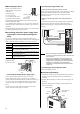
• Note on connecting a power supply whose positive terminal
is grounded
The data edit connector (CN4) and analog I/O signals connector
(CN6) are not insulated. When grounding the positive terminal of the
power supply, do not connect any equipment (PC, etc.) whose
negative terminal is grounded. Doing so may cause the driver and
these equipment to short, damaging both. Use the data setter
OPX-2A to set data, etc.
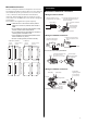
Installation
Location for installation
The driver is designed and manufactured for installation in
equipment.
Install it in a well-ventilated location that provides easy access for
inspection. The location must also satisfy the following conditions:
• Inside an enclosure that is installed indoors (provide vent holes)
• Operating ambient temperature 0 to +50 °C (+32 to +122 °F)
(non-freezing)
• Operating ambient humidity 85% or less (non-condensing)
• Area that is free of explosive atmosphere or toxic gas (such as
sulfuric gas) or liquid
• Area not exposed to direct sun
• Area free of excessive amount of dust, iron particles or the like
• Area not subject to splashing water (rain, water droplets), oil (oil
droplets) or other liquids
• Area free of excessive salt
• Area not subject to continuous vibration or excessive shocks
• Area free of excessive electromagnetic noise (from welders,
power machinery, etc.)
• Area free of radioactive materials, magnetic fields or vacuum
• Up to 1000 m (3300 ft.) above sea level