
User manual

8
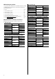
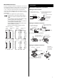
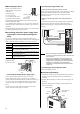
Connecting the motor
• Connection example
(The electromagnetic brake motor)
Connect to CN2
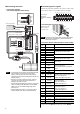
CN1 connector
Connect to CN1
Connect to CN5
Cable for electromagnetic brake
Cable for encoder
Encoder cable
Electromagnetic
brake cable
Cable for motor
Motor cable
24 VDC±10%
0.8 A or more
24 VDC power supply
䋭
䋫
MB1
MB2
24 V+
24 V
-
CN2 connector
U
V
W
Tightening torque:
1.2 N·m (170 oz-in.)
Black
White
Red
White
Black
Phase
Note
• The lead wires of the cable for electromagnetic brake
have polarities, so connect them in the correct
polarity. If the lead wires are connected with their
polarities reversed, the electromagnetic brake will not
operate properly.
• Have the connector plugged in securely. Insecure
connector connection may cause malfunction or
damage to the motor or driver.
• When plugging/unplugging the connector of the motor
cable, turn off the power and wait for the CHARGE
LED to turn off. The residual voltage may cause
electric shock.
• When installing the motor to a moving part, use an
optional flexible cable offering excellent flexibility.
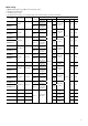
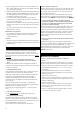
Connecting the I/O signals
Solder the I/O signal cable (AWG28 to 26: 0.08 to 0.14 mm
2
) to the
CN7 connector (36 pins). Use a shielded cable for I/O signals.
Connector pin
assignment
(viewed from soldering
side)
1
2
3
4
5
6
7
8
9
10
11
12
13
14
15
16
17
18
19
20
21
22
23
24
25
26
27
28
29
30
31
32
33
34
35
36
• Connecting the connector (CN7)
Tightening torque:
0.3 to 0.35 N·m
(42 to 49 oz-in)
CN7
Screw
Note
Be certain the I/O signals cable is as short as possible.
The maximum input frequency will decrease as the
cable length increases.
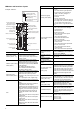
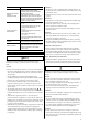
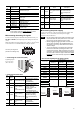
• Connector function table (Position control mode)
Pin
No.
Signal name Name
1 − −
2 GND Ground connection
3 ASG+
4 ASG−
A-phase pulse line-driver output
5 BSG+
6 BSG−
B-phase pulse line-driver output
7 ZSG1+
8 ZSG1−
Z-phase pulse line-driver output
9 ALM+
10 ALM−
Alarm output
11
WNG+/MOVE+
∗
/
MBC+
∗
12
WNG−/MOVE−
∗
/
MBC−
∗
Warning output/
Motor moving output
∗
/
Electromagnetic brake control signal
output
∗
13 END+
14 END−
Positioning complete output
15
READY+/AL0+
∗
/
P-OUTR+
16
READY−/AL0−
∗
/
P-OUTR−
Operation ready complete output/
Alarm code output bit 0
∗
/
Position data output ready output
17
TLC+/AL1+
∗
/
P-OUT0+
18
TLC−/AL1−
∗
/
P-OUT0−
Torque limit output/
Alarm code output bit 1
∗
/
Position data output bit 0
19
ZSG2+/NEAR+
∗
/
AL2+
∗
/P-OUT1+
20
ZSG2−/NEAR−
∗
/
AL2−
∗
/P-OUT1−
Z-phase pulse open-collector output/
Near position output
∗
/
Alarm code output bit 2
∗
/
Position data output bit 1
21 GND Ground connection
22 IN-COM Input common
23 S-ON Servo on input
24
CLR/ALM-RST/
P-CK
Deviation clear input/Alarm reset input/
Position data transmission clock input
25 P-REQ Position data request input
26 TL Torque limit enable input
∗ The signal will become effective if the applicable setting has been changed
using the data setter OPX-2A or the data setting software MEXE02.