
User manual

9
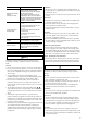
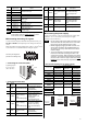
Pin
No.
Signal name Name
27 M0
28 M1
Data selection input
29 P-PRESET Position preset input
30 FREE Shaft free input
31 CW+/PLS+
32 CW−/PLS−
CW pulse input/
Pulse input
33
CW+24 V/
PLS+24 V
CW pulse/
pulse input for 24 V
34
CCW+24 V/
DIR+24 V
CCW pulse input/
direction input for 24 V
35 CCW+/DIR+
36 CCW−/DIR−
CCW pulse input/
Direction input
Note
Functions of the connector vary depending on the
control mode. Check the USER MANUAL
for other
control modes except position control mode.
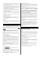
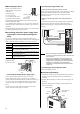
Connecting the analog I/O signals
Use the connector (20 pins) included in the optional accessory set
AS-SV2 or AS-SD1 (sold separately) as the analog I/O connector
(CN6).
Solder the analog I/O cable (AWG28 to 26: 0.08 to 0.14 mm
2
) to the
CN6 connector. Use a shielded cable for analog I/O signals.
Connector pin assignment
(viewed from soldering side)
1
2
3
4
5
6
7
8
9
10
11
12
13
14
15
16
17
18
19
20
• Connecting the connector (CN6)
Tightening torque:
0.3 to 0.35 N·m
(42 to 49 oz-in)
CN6
Screw
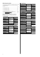
• Connector function table
Pin
No.
Signal
name
Name Description
1 V-REF
Analog speed
(command/limit) input
Terminal used to input an
analog speed
(command/limit).
2 SG Signal ground Ground for analog I/Os.
3 P-VREF
Reference voltage
output for analog
speed
(command/limit) input
A power supply output
used to connect a
variable resistor to the
analog speed
(command/limit) input.
4 P-TREF
Reference voltage
output for analog
torque
(command/limit) input
Power supply output used
to connect a variable
resistor to the analog
torque (command/limit)
input.
5 T-REF
Analog torque
(command / limit)
input
Terminal used to input an
analog torque
(command/limit).
6 SG Signal ground Ground for analog I/Os.
Pin
No.
Signal
name
Name Description
7 V-MON
Analog speed monitor
output
Voltage corresponding to
the monitored analog
speed is output from
here.
8 SG Signal ground Ground for analog I/Os.
9 T-MON
Analog torque
monitor output
Voltage corresponding to
the monitored analog
torque is output from
here.
10 SG Signal ground Ground for analog I/Os.
11
to
20
− − −
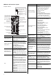
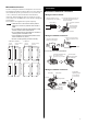
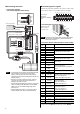
Connecting the power supply
Use the CN3 connector (7 pins) to connect the power supply cable
(AWG16 to 14: 1.25 to 2.0 mm
2
) to the main power supply
connector (CN3) on the driver.
Note
• Do not wire the power supply cable of the driver in the
same cable duct with other power line or motor cable.
Doing so may cause malfunction due to noise.
• Before plugging/unplugging the CN3 connector, turn
off the power and wait for the CHARGE LED to turn
off. Failure to do so may cause electric shock due to
residual voltage.
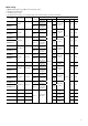
• The current capacity for the power supply as shown
below is the value when operating the motor in the
continuous duty region. When operating in the limited
duty region, the current will flow maximum three times
as much as the continuous region. Refer to the USER
MANUAL for the continuous duty region and limited
duty region.
• The current capacity for the power supply
Current capacity
Unit model
Single-phase
100-115 V
Single-phase
200-230 V
Three-phase
200-230 V
NX45 1.9 A or more 1.2 A or more 0.7 A or more
NX410 2.9 A or more 1.8 A or more 1.0 A or more
NX65 1.9 A or more 1.2 A or more 0.7 A or more
NX610 2.9 A or more 1.8 A or more 1.0 A or more
NX620 4.6 A or more 2.8 A or more 1.6 A or more
NX640 − − 2.8 A or more
NX810 2.8 A or more 1.8 A or more 1.0 A or more
NX820
NX920
4.6 A or more 2.8 A or more 1.6 A or more
NX940 2.8 A or more
NX975 4.7 A or more
NX1040 2.9 A or more
NX1075
− −
4.7 A or more
100-115 V
50/60 Hz
• Single-phase
100-115 V
• Single-phase
200-230 V
• Three-phase
200-230 V
L
N
R
S
T
200-230 V
50/60 Hz
200-230 V
50/60 Hz
L1
L2