Always "On" UPS Systems Inc. ® NX Series 3 Phase UPS System 10kVA to 160kVA Service Manual Version 2.16 Always “On” UPS Systems Inc. Bldg 1 - 150 Campion Road, Kelowna, BC, Canada, V1X 7S8 Phone: (250) 491-9777 Ext. 451, Fax: (250) 491-9775, Email: sales@alwayson.
Always On UPS Systems Inc
Always On UPS Systems Inc Table of Contents 1. SAFETY INSTRUCTIONS......................................................................................................................... 1 GENERAL BLOCK DIAGRAM................................................................................................................ 2 6 PULSE RECTIFIER TOPOLOGY DRAWING.................................................................................... 3 4. 12 PULSE RECTIFIER TOPOLOGY DRAWING..........................
Always On UPS Systems Inc 1. SAFETY INSTRUCTIONS This Safety Notice is addressed to the Always “On” customer engineers who perform maintenance of the Uninterruptible Power Supply (UPS) systems. Electrical Safety • Maintenance work to be preformed by factory trained customer engineers or qualified personnel. Extremely dangerous voltage levels can exist within the UPS system; extreme caution must be used. • Ensure system is in maintenance bypass mode or external wrap-around bypass mode before work is started.
Always On UPS Systems Inc 2. GENERAL BLOCK DIAGRAM Figure 2.1 General Block Diagram Normal Operation: The rectifier/charger converts the supplied AC power into DC (bus) power, which is then supplied to the inverter and the battery charger. The DC to AC inverter then supplies continuous, noise free AC power to the critical loads. The inverter output is synchronized with the bypass AC power source provided that the bypass AC power source is within the specified frequency range.
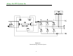
Always On UPS Systems Inc 3. 6 PULSE RECTIFIER TOPOLOGY DRAWING BYPASS P.S. STATIC SWITCH RESERVE P.S. OUTPUT R RESV INVERTER AUTO-TRANS RECTIFIER FILTER S STATIC SWITCH T 6 PULSE RECTIFIER INPUT N INPUT OPV R S RECV T Figure 3.1 Always “On” UPS Systems Topology - 3 Phase UPS 6 Pulse Rectifier Input: 3PH-4W Output: 3PH-4W Zero Degrees Phase Shift BAT. POS. N FIL FILTER BAT. NEG.
Always On UPS Systems Inc 4. 12 PULSE RECTIFIER TOPOLOGY DRAWING BYPASS P.S. STATIC SWITCH RESERVE P.S. OUTPUT R RESV INVERTER AUTO-TRANS RECTIFIER INPUT FILTER S STATIC SWITCH T 12 PULSE RECTIFIER N INPUT R OPV S T N FIL Figure 4.1 Always “On” UPS Systems Topology - 3 Phase UPS 12 Pulse Rectifier Input: 3PH-4W Output: 3PH-4W Zero Degrees Phase Shift RECV FILTER BAT. POS. BAT. NEG.
Always On UPS Systems Inc 5. RECTIFIER The main function of a rectifier is to convert the AC input power to DC power. The DC power is then used to charge the batteries, supply the DC bus, which in turn supplies the inverter. Figure 5.1 Rectifier Block Diagram The rectifier design used in the 10kVA to 60kVA UPS’s include a 6-pulse full controlled rectifier. Power Factor Correction (PFC) has been added to maintain a high input power factor, independent of the load power factor.
Always On UPS Systems Inc Figure 5.
Always On UPS Systems Inc 6. INVERTER Figure 6.1 Inverter Layout The inverter is composed of IGBT’s, inductors, capacitors, highly efficient filters, control circuitry and protection circuitry. This inverter inverts the DC power received on the DC bus to isolated, noise-free AC power, which is then supplied to the critical loads. Our PWM wave generator is switching at a higher frequency well above the human audible range.
Always On UPS Systems Inc Figure 6.
Always On UPS Systems Inc 7. STATIC SWITCH Figure 7.1 Static Bypass The static switch is composed of two pairs of back to back naturally commutated SCR’s, which moves the load from inverter to reserve (utility) or from reserve to inverter without interruption of power to the load. Detection circuitry is included in the control circuit to achieve “0” dead time transfer. Additional detection is employed to control the static switch transfer.
Always On UPS Systems Inc Figure 7.
Always On UPS Systems Inc 8. INTER-PCB DIAGRAM Figure 8.
Always On UPS Systems Inc 9. PCB MODULE Figure 9.
Always On UPS Systems Inc 10. AUXILARY POWER SUPPLY STFAN ACPS 180Vac 120Vac L1 OUTPUT 4A 0 Vac 250 Vac SSPS 120Vac RESERVE 8A 17 Vac ST9632 DC BUSS (BATT V) 2 SNMP 3 1 6 POWER SUPPLY 6 5 3B UPPER FAN 4A LOWER FAN 3J 8 120Vac 30Vac ST9632 4 3 MAIN CONTROL 1 BOARD 11 3A 9 10 4 7 POWER SUPPLY COMMUNICATIONS 5 BOARD 3R Figure 10.1 Detailed drawing of the Aux.
Always On UPS Systems Inc 11. STARTUP PROCEDURES Using the following procedure below start up the UPS, or use “manual bypass to inverter procedure”. 11.1. System start up (from complete shutdown) Follow Step by step - confirming each operation Use the Status Indicator Table as a guideline. Note: Proceed until a failure mode occurs – then record status of indicators and step failure occurred. If fault cleared during start up Do operational checks of all UPS functions.
Always On UPS Systems Inc h. i. j. k. Fans will start, output voltage will be present. Indicators will show normal inverter operation of the system. Turn Inverter Off – push buttons on front panel. - This will turn the inverter OFF and put the UPS in Static bypass mode. Reserve power will feed the output of the UPS. The switch from inverter to reserve power should be seamless and uninterrupted. Indicators will show Static Bypass status. Turn Inverter ON – push buttons on front panel.
Always On UPS Systems Inc c. d. e. f. g. h. i. j. k. - Status LEDs indicate status of sub-systems – many alarm indicators will be illuminated as the rectifier does not yet have AC power applied, and the DC buss has not been established; Battery Low Stop, low battery, fuse/temp, Rectifier AC Fail, Rotation Error Push the OFF button (0) on front panel to clear alarm indicators on the Main Control PCB. Open the Bypass breaker.
Always On UPS Systems Inc - Indicators will show normal rectifier and inverter operation of the system. Record UPS status o Out of service, bypass mode o Status form 12. UPS SHUTDOWN PROCEDURES 12.1. Complete UPS shut down procedure a. Switch off the inverter – The inverter can be switched off by simultaneously pressing the inverter off switch (O) and the inverter control switch (◄►). The load will be automatically transferred to reserve without interruption. b.
Always On UPS Systems Inc d. Close the Bypass breaker – The reserve breaker and reserve static switch are still conducting. When the maintenance bypass breaker is closed, power will flow through the bypass loop instead of the reserve loop because the impedance of the bypass loop is lower. e. Open the Reserve breaker – You can now open the reserve breaker to put the ups into manual bypass.
Always On UPS Systems Inc 13. LCD DISPLAY AND LED DESCRIPTION Before powering down the system to perform service or maintenance, record the readings and all the LED’s that are illuminated on the Front Panel Status Report Log. This will aid in identifying the status of the UPS system prior to shutdown. Below is a reference list for possible LED notification and readings on the LCD display. E I K L B C F G H A D J P Q Figure 13.
Always On UPS Systems Inc The front panel is located behind the glass window on the front door. It displays the real time information, UPS Status, battery system and provides the user interface for controlling and setting the UPS operating parameters. This panel is user friendly. Each part of the panel is explained below: A: LCD display- Real time status, data and historical events are displayed on the LCD. The UPS parameters, real time clock, inverter, and buzzer can also be set through this LCD.
Always On UPS Systems Inc • • • • • • • • • • • • • • • • • • • • • • SHORT CIRCUIT – UPS output is in a short circuit state. FUSE/OVER TEMP SD – inverter has shutdown due to inverter fuse open or heat sink temperature above operating parameters. INVERTER FAIL SHUTDOWN – inverter has shutdown due to inverter output voltage below tolerances. BYPASS ON SHUTDOWN – inverter has shutdown because the bypass breaker has been activated while the inverter is supplying power to the load.
Always On UPS Systems Inc • BACK-UP • • • • • • INVERTER IS SHORT CIRCUITED INVERTER FUSE OPEN HEAT SINK OVER TEMPERATURE HIGH DC SHUTDOWN BYPASS ON STOP EMERGENCY STOP >125%, beep once / second >150%, beep twice / second >320VDC, beep once / 3 seconds <320VDC, beep twice / second <295VDC, no beeping beep continuously beep continuously beep continuously beep continuously beep continuously beep continuously The buzzer will beep once every time the inverter is switched on or off.
Always On UPS Systems Inc M. Up key: This is an LCD control key. It moves the cursor one field upward when items are being selected or changes the number/character forward when data or parameters of the UPS are being set. N. Down key: This is an LCD control key. It moves the cursor one field downward when items are being selected or changes the number/character backward when data or parameters of the UPS are being set. O. Enter key: This is an LCD control key.
Always On UPS Systems Inc 14. THE LCD DISPLAY The LCD displays Real Time information as to the status and operation characteristics of the UPS system and battery banks. In order to make the display sharp and readable, the LCD is back-lit by LED’s. To prolong the life of the LED, the CPU will cut off the power of the LED 3 minutes after the last key has been pressed. The backlight will illuminate whenever a key has been pressed. This screen will pop up once the system power is enabled (i.e.
Always On UPS Systems Inc 14.2. Menu 1 – Select Menu S E L E C T S T A T U S R E A L WA R N I N G T I ME H I S T OR I C A L ME N U F A U L T P A R A ME T E R S E T D A T A D A T A E X I T Figure 14.2.1 Select Menu Display MENU 1 is reached by pressing any button on the opening screen and is also the default menu. From this menu the personnel can select STATUS WARNING FAULT (MENU 2 – Section 10.3), REAL TIME DATA (MENU 3 – Section 10.4), HISTORICAL DATA (MENU 4 – Section 10.
Always On UPS Systems Inc 14.3. Menu 2 – Status Warning Menu S T A T U S WA R N I N G R E C T I F I E R = ON I N V E R T E R = ON L OA D ON I N V E R T E R Figure 14.3.1 Status Warning Menu Display The Status/Warning menu is accessed through MENU 1 by selecting STATUS WARNING FAULT. The left-hand side of this menu shows the real time status of the rectifier, inverter and static switch, while the right hand side shows the warning or fault condition if any.
Always On UPS Systems Inc Listed below are all the fault conditions that can be displayed: 1st row: HIGH DC SHUTDOWN – DC Bus voltage out of operating range. 2nd row: SHORT CIRCUIT! – a short circuit condition has occurred on the output. FUSE/OVERHEAT – a fuse has blown or the system has shutdown due to overheating. OVERLOAD SHUTDOWN – system has exceeded the overload limit beyond the operating window. EMERGENCY STOP – user has activated the emergency stop feature.
Always On UPS Systems Inc 14.5. Menu 4 – Historical Event Menu DA 2 0 0 2 \ 0 2 0 0 2 \ 1 2 0 0 3 \ 0 T 3 1 3 E T I ME E \ 2 9 0 9 : \ 0 1 2 2 : \ 1 0 1 5 : V 3 1 4 ENT S 2 5 7 > R U N : 2 1 Y R 0 3 MO Figure 14.5.1 Historical Event Menu Display MENU 4 is reached by selecting HISTORICAL DATA on MENU 1. All abnormal events are stored on the EEPROM and viewed through this menu based on the time each event occurred.
Always On UPS Systems Inc 14.6. Menu 5 – Parameter Setting Menu P A R A ME T E R I N V E R T E R = ON / OF F S E T T I N G D A T E T I ME B U Z Z E R = ON / OF F B OOS T C H A R GE E X I T Figure 14.6.1 Parameter Setting Menu Display MENU 5 is reached by selecting PARAMETER SET on MENU 1 and access is only allowed if the correct password is entered. The cursor (→) is used to select which parameter the user would like to edit, such as INVERTER ON/OFF, BUZZER ON/OFF, BOOST CHARGE, DATE/TIME.
Always On UPS Systems Inc R E C T I F I E R R E C T I F I E R R - N = X X X V a c D A T A > F R E QU E N C Y = X X S - N = X X X V a c H Z T - N = X X X V a c Figure 14.7.1 Rectifier Data Menu Display 14.7. Menu 6 – Rectifier Data Menu MENU 6 is reached by selecting RECTIFIER DATA on MENU 3.
Always On UPS Systems Inc 14.9. Menu 8 – Output Data Menu OU T P U T OU T P U T L OA D : R = X X X R - N = X X X V a c D A T A F R E QU E N C Y = X X % S = X X X S - N = X X X % V a c H Z T = X X X % T - N = X X X V a c Figure 14.9.1 Output Data Menu Display MENU 8 is reached by selecting OUTPUT DATA on MENU 3.
Always On UPS Systems Inc 14.11. Menu 10 – Boost Charge Setting Menu Warning! These settings have been preset by the factory to optimize the battery bank requirements. Do not change settings unless factory or factory trained service personnel have been consulted. B OOS T C H A R GE S E T T I N G A U T O- B OOS T ( MON T H ) = 0 4 A U T O- B OOS T ( B A T T C H A R GE L O W) = 0 8 C U R R E N T = L O E X I T Figure 14.11.
Always On UPS Systems Inc B O O S T C H A R G E S E T T I N G A U T O - B O O S T ( MO N T H ) = 0 4 A U T O - B O O S T ( B A T T C H A R G E L O W) = 0 4 0 8 1 2 1 6 C U R R E N T = L O 2 0 2 4 E X I T Figure 14.11.3 Boost Charge Setting Menu Display Program Settings CHARGE CURRENT increases the amount of charge current the rectifier/charge supplies the battery bank. There are three possible options (LO/ME/HI).
Always On UPS Systems Inc 14.12. Menu 11 – Data Time Setting Menu D A T E T I ME S E T T I N G Y E A R =X X X X H OU R ( 2 4 H ) = X X MON T H = X X MI N U T E = X X D A Y = X X D A Y OF T H E WE E K = M O N E X I T Figure 14.12.1 Data Time Setting Menu Display MENU 11 is reached by selecting DATE/TIME on MENU 5. This menu allows the user to set the YEAR, MONTH, DAY, HOUR, MINUTE and DAY OF THE WEEK of the real time clock.
Always On UPS Systems Inc 15.
Always On UPS Systems Inc 16.
Always On UPS Systems Inc 17. BOARD FAULT DIAGRAMS 3A Board Fault UPS will not start up. Once Reserve Breaker is closed all LED’s on front display light up and LCD is non-functional.
Always On UPS Systems Inc 3B Board Fault UPS will not start up. Once Reserve Breaker is closed all LED’s on front display light up and LCD is non-functional.
Always On UPS Systems Inc 3CC Board Fault UPS will not start-up. Rectifer disabled. No DC Buss.
Always On UPS Systems Inc 3R Board Fault No front panel display and no communications. UPS starts up as per normal operation and inverter and rectifier function as per normal operation.
Always On UPS Systems Inc 3T Board Fault A UPS system initializes ok. Once inverter attempts to assume load system beeps, “Inv Fail Shutdown” LED turns on, “Fault” LED turns on and “Load” LED flashes. System remains in Static Bypass mode, re-attempting Inverter start-up continually.
Always On UPS Systems Inc 3T Board Fault B UPS system initializes ok. Once inverter attempts to assume load system beeps, “Inv Fail Shutdown” LED turns on and “Fault” LED turns on. System remains in Static Bypass mode.
Always On UPS Systems Inc Inverter Module Fault UPS system initializes ok. When DC Buss is established “Fuse/Temp” fault LED turns on. Inverter can not be turned on. System operates in Static bypass mode only.
Always On UPS Systems Inc Static Switch Module Fault UPS starts up to full operation. When inverter is turned off UPS output shuts down because of faulty static switch.
Always On UPS Systems Inc 18. BATTERY CABINET The battery cabinets have been designed with the same style and appearance as the UPS cabinet for ease of installation and cosmetic value. Re-enforcement has been added to strengthen the cabinet for the additional weight and transportation. The Battery Banks contain the batteries and provide the runtime for the UPS system. Figure 18.
Always On UPS Systems Inc Figure 18.
Always On UPS Systems Inc + + + + + + + + + + + + + TOP TRAY + LOWER THREE TRAYS (NOTE: BOTTOM TRAY HAS ONLY 7 BATTERIES) Always "On" UPS Systems BATTERY CAB A BATTERY TRAY WIRING LAYOUT FILE: BATTERY CAB A - 0001 DATE: 050112 47 VERSION: V1.0 PROJECT: BATTERY CAB A Kelowna B.C. alwaysonups.com PH:877-259-2976 Reproduction and/or use without express permission is prohibited by law.
Always On UPS Systems Inc + 125A BREAKER + POS NEG TOTAL: 348VDC / 60A + + Always "On" UPS Systems BATTERY CAB A BATTERY INTERCONNECT WIRING CONFIG FILE: BATTERY CAB A - 0002 DATE: 050112 48 VERSION: V1.0 PROJECT: BATTERY CAB A Kelowna B.C. alwaysonups.com PH:877-259-2976 Reproduction and/or use without express permission is prohibited by law.
Always On UPS Systems Inc + + + + + 125A BREAKER + 125A BREAKER + POS NEG TOTAL: 348VDC / 250A + Always "On" UPS Systems BATTERY CAB B BATTERY INTERCONNECT WIRING CONFIG FILE: BATTERY CAB B - 0001 DATE: 050112 49 VERSION: V1.0 PROJECT: BATTERY CAB B Kelowna B.C. alwaysonups.com PH:877-259-2976 Reproduction and/or use without express permission is prohibited by law.
Always On UPS Systems Inc + + + + + + + + + + + + + TRAY 4 & TRAY 5 + TRAYS 2,3,6,7 NOTE: TRAY 1 (BOTTOM TRAY) & TRAY 8 (TOP TRAY) HAVE ONLY 7 BATTERIES EACH Always "On" UPS Systems BATTERY CAB B BATTERY TRAY WIRING LAYOUT FILE: BATTERY CAB B - 0002 DATE: 050112 50 VERSION: V1.0 PROJECT: BATTERY CAB B Kelowna B.C. alwaysonups.com PH:877-259-2976 Reproduction and/or use without express permission is prohibited by law.
Always On UPS Systems Inc - TOP TRAY + + - + - + - + MIDDLE TRAY - + + - + - BOTTOM TRAY - - + + + - + - + - - + + - + - + - + - - + + - - + - - + + - + + + + - - - + + BLK RED RED TOTAL: 348VDC 350A BLK RED RED B+ B- Always "On" UPS Systems BATTERY CAB C 29 BATT. WIRING DIAGRAM FILE: BATTERY CAB C - 0001 DATE: 050112 51 VERSION: V1.0 PROJECT: BATTERY CAB C Kelowna B.C. alwaysonups.
Always On UPS Systems Inc - TOP TRAY + + - + - + - + MIDDLE TRAY - + - + - + + - BOTTOM TRAY + - + - - + + - + - + - + + - - + - - - + + + + + - - + - + + - + - - + + BLK RED RED TOTAL: 348VDC 500A BLK RED RED B+ B- Always "On" UPS Systems BATTERY CAB E 29 BATT. WIRING DIAGRAM FILE: BATTERY CAB E - 0001 DATE: 041228 52 VERSION: V1.0 PROJECT: BATTERY CAB E Kelowna B.C. alwaysonups.
Always On UPS Systems Inc 18.1.
Always On UPS Systems Inc 19. MAIN CONTROL (3A PCB) The Main Control PCB monitors and controls all the major components within the UPS system. Through the various monitoring devices and PCB’s (mentioned later in this manual) it provides all the control signals, synchronizing signals and various conditions to the UPS system and Operator interfaces. Figure 19.
Always On UPS Systems Inc LED A1 LED A2 LED A3 LED A5 LED A4 Picture 19.
Always On UPS Systems Inc Table 19.
Always On UPS Systems Inc 20. POWER SUPPLY (3B PCB) This is the main power supply for the PCB and is the interface between the Main Control PCB and the Battery supply. It provides battery condition information to the Main Control PCB to control the Rectifier/Charger. It also provides visual indication of the charging mode. Figure 20.
Always On UPS Systems Inc Picture 20.1 3B PCB (Power Supply) LED B2 LED B6 LED B4 LED B7 PCB 3B FUNCTION Power Supply LOCATION LED B3 LED B1 NORMAL LED Description PCB LED Illuminated LED B1, B2, B3, B4 All Yes LED B6 Yes LED B7 Yes PCB has power PCB Module The system is testing the batteries The system is boost charging the batteries. Table 20.
Always On UPS Systems Inc 21. RECTIFIER CONTROL CIRCUIT (3C PCB) This PCB acts as the interface between the Main Control PCB and the Rectifier Module. It relays the control signals from the Main Control PCB to the Rectifier Driver (3S PCB) within the Rectifier Module. It also monitors all aspects of the Rectifier Module. This information is then forwarded to the Main Control PCB as part of the control loop. Figure 21.
Always On UPS Systems Inc LED C2 LED C3 LED C1 Picture 21.1 3C PCB (6 Pulse Rectifier Driver) LED C2 LED C3 LED C1 Picture 21.2 3C and 3CC PCB (12 Pulse Rectifier Driver) Table 21.
Always On UPS Systems Inc 22. INVERTER PHASE CONTROL (3T PCB) This PCB acts as the interface between the Main Control PCB and each phase of the Inverter Module. It relays the control signals and inverter drive waveforms from the Main Control PCB to the Inverter Driver (3G PCB) within each phase of the Inverter Module. It also monitors all aspects of the Inverter Module. This information is then forwarded to the Main Control PCB as part of the control loop. Figure 22.
Always On UPS Systems Inc Picture 22.1 3T PCB (Inverter Driver) LED T1 LED T2 Table 22.1 LED Operation for the 3T PCB PCB 3T FUNCTION LOCATION Inverter Phase Control PCB Module NORMAL LED PCB LED Description Illumination LED T1, T2 All Yes PCB has power 62 ABNORMAL SOLUTION LED Description Illumination R, S or T phase lost, output LED on the Ensure cable connections are secure All No front panel (mimic and correctly attached. diagram) blinks indicating lost phase.
Always On UPS Systems Inc 23. COMMUNICATIONS INTERFACE (3R PCB) This is the local and remote Operator interface for the entire UPS system. This controls the local front panel Operator interface by utilizing information from the Main Control PCB and translating and sending that to the front panel display PCB’s. Also receives the local Operator commands from front panel display PCB’s and relays these to the Main Control PCB.
Always On UPS Systems Inc Picture 23.1 3R PCB (Communications Interface) LED R1 Table 23.1 LED Operation for the 3T PCB PCB FUNCTION LOCATION 3R Communication Interface PCB Module PCB LED LED R1 NORMAL LED Illumination Yes Description PCB has power 64 ABNORMAL LED Description Illumination No SOLUTION Ensure cable connections are Interface secure and correctly attached.
Always On UPS Systems Inc 24. WARNING LED’S AND SWITCHES (3W PCB) 25. LCD DISPLAY 26. MIMIC DIAGRAM (3L PCB) 27. STATUS LED’S AND AUDIBLE ALARM (3AG PCB) These PCBs make up the local operator display and control interface. Figure 24.
Always On UPS Systems Inc 28. RECTIFIER MODULE This is a pluggable module which contains the high power devices for the rectifier / charger. The rectifier converts the power from the AC utility to regulated and conditioned DC power, which is used to charge the batteries and supply the DC Bus. The rectifier can be configured as a 6-pulse or 12-pulse rectifier system. The rectifier is comprised of a Rectifier Driver (3S PCB), high powered SCRs and other monitoring and protection components.
Always On UPS Systems Inc RECTIFIER MODULE Figure 28.
Always On UPS Systems Inc Static Switch R Phase S Phase T Phase 6-pulse Rectifier Picture 28.
Always On UPS Systems Inc Table 28.1 Operation for the 3S PCB PCB 3S FUNCTION Rectifier Drive LOCATION PCB LED NORMAL LED Illumination ABNORMAL LED Description Illumination Description If DC bus can not be stabilized, the AC output is transferred to the reserve automatically Rectifier Module SOLUTION Ensure cable connections are secure and correctly attached. The expected MTBF for this system is 3,000,000 minutes.
Always On UPS Systems Inc 29. INVERTER MODULE This is a pluggable module which contains the high power devices for the inverter. The inverter converts the power from the DC Bus to regulated and conditioned AC power. One phase of the inverter is comprised of an Inverter Driver PCB (3G PCB), high powered IGBTs, a Protection Fuse and other monitoring and protecting components. INVERTER MODULE Figure 29.
Always On UPS Systems Inc S INVERTER MODULE T INVERTER MODULE R INVERTER MODULE Figure 29.
Always On UPS Systems Inc R phase LED G1 S phase T phase Picture 29.
Always On UPS Systems Inc Table 29.1 LED Operation for the 3G PCB PCB FUNCTION LOCATION 3G Inverter Driver (RST) Inverter Module PCB LED LED G1 NORMAL LED Illumination Yes Description Inverter working ABNORMAL LED Description Illumination No Figure 29.3 Layout of one phase of the Inverter Module 73 Inverter failure SOLUTION Ensure cable connections are secure and correctly attached.
Always On UPS Systems Inc 30. STATIC SWITCH This is a pluggable module, which is either part of the Rectifier Module (for the 10kVA to 60kVA UPS systems) or a separate module (80kVA to 160kVA UPS systems) containing the high power devices for the static switch. The static switch monitors the inverter and output. If a condition occurs (inverter shutdown or problem condition), it will transfer the output from the inverter to the reserve path automatically.
Always On UPS Systems Inc STATIC SWITCH MODULE Figure 30.
Always On UPS Systems Inc Static Switch R Phase S Phase P2 LED P1 LED T Phase Picture 30.
Always On UPS Systems Inc Table 30.1 LED Operation for the 3P PCB PCB FUNCTION 3P Static Switch Driver (R,S,T) NORMAL ABNORMAL SOLUTION LED LED Description Description Illumination Illumination Inverter output is within Inverter operating, transfer LED P1 Yes No Replace the board Static Switch normal parameters from inverter has failed Module Reserve output is within Inverter operating, transfer LED P2 Yes No Replace the board normal parameters from reserve has failed LOCATION PCB LED Figure 30.
Always On UPS Systems Inc 31. AUXILIARY POWER SUPPLY Designed as a secondary and redundant power supply to the one located within the UPS module. The main function of the auxiliary power supply is to provide power to the fans and an alternate supply for the main CPU board. Picture 31.1 3J board (Auxiliary Power Supply) Figure 31.
Always On UPS Systems Inc ! WARNING Da ngerous A C & DC P HIG H V O LTAG E ! Operati ng Proced ure Warn n i g: For Installation & First Time Startup, Please Se St artup Pr ocedure 1. Close the INPUT bre aker.P2. Close the RESER VE bre aker.P3. Close the RECTIFIER breake r. P4 . Wait 30 secoundfor the DC bu s P vo tlage to rise .The warning LEDsP "BAT LOW" and 'BAT LOW STO P" P on th e front panel will turn o ff.P5. Close the BATTER Y breaker/P fuses.P6.
Always On UPS Systems Inc CNB2 CNB7 LCD PANEL CNB6 CNB1 CNC1 3B 3C RECTIFIER CONTROL POWER SUPPLY STATUS WARNING G G R R LED PANEL & BEEPER MIMIC PANEL Y CNC4 CNB6 CNA8 CNA7 CNA2 TO S.S. MODULE R R 3A R MAIN CONTROL R R CNA5 CNA4 LED PANEL & SWITCHES G TO REC.
Always On UPS Systems Inc PS LOWER FAN SS PS O/P R CAP AC CAP O/P O/P S T CAP IN IR IS IT OR OS OT ON B+ B- Figure 31.
Always On UPS Systems Inc Figure 31.
Always On UPS Systems Inc Figure 31.7 Layout view of the left side of the system with the panel off Figure 31.8 Layout view of the back of the system with the panel off 83 Figure 31.
Always On UPS Systems Inc Figure 31.
Always On UPS Systems Inc START PROCEDURE: SHUTDOWN PRO CEDURE: 1. CLOSE THE RESERVE BREAKER. 2. CLOSE THE RECTIFIER BREAKER. 1. PUSH T HE INVERTEROF F SWIT CH (RIGHT & MIDDLEOF INVERT ER 3. WAI T 30sec FOR DC VOLTAGERISE UP. 4. CLOSE THE BAT TERY BREAKER. 5. PUSH INVERTER O N SWITCH (LEFT & MIDDLE OF INVERTER SWITCH). 6. THE LOAD WIL L TRANSFER T O INVERTER OUT PUT AFT ER 7sec . 7. LOCK THE DOOR. FROM BYPASS TO INVERTER SWITCH). 2. OPEN THE BAT TERY BREAKER. 3. OPEN THE RECT IFIERBREAKER. 4.
Always On UPS Systems Inc Figure 31.
Always On UPS Systems Inc Figure 31.
Always On UPS Systems Inc Figure 31.
Always On UPS Systems Inc Figure 31.15 Layout view of the left side of the system with the panel off Figure 31.
Always On UPS Systems Inc Figure 31.
Always On UPS Systems Inc Section A SINGLE LINE DRAWINGS
Always On UPS Systems Inc BYPASS N G NFB–3P 4W+G RES TO LOAD PANEL 3PH 4W+G S.S. RECT RECT INV S.S.
Always On UPS Systems Inc BYPASS ISO. TRANS. NFB - 3P 4W+G N-G BONDED UPS INPUT TO LOAD PANEL 3PH 4W+G UPS OUTPUT BYPASS RES S.S. RECT RECT INV S.S.
Always On UPS Systems Inc Section B PARTS LIST FOR ALL SYSTEMS Recommended Spare Parts for the NX Series UPS Systems Item Part No.
Always On UPS Systems Inc 32. CONTACT INFORMATION 32.1. Additional Purchases or Upgrades Always “On” UPS Systems Inc. Bldg 1 – 150 Campion Road, Kelowna, BC, Canada, V1X 7S8 Phone: (250) 491-9777 Ext 451 Fax: (250) 491-9775 Email: sales@alwaysonups.com Website: www.alwaysonups.com 32.2. QA / Warranty Questions Always “On” UPS Systems Inc. Bldg 1 – 150 Campion Road, Kelowna, BC, Canada, V1X 7S8 Phone: (250) 491-9777 Ext 209 Fax: (250) 491-9775 Email: qa@alwaysonups.com Website: www.alwaysonups.