Service manual
Manuals
Brands
Always "On" UPS Manuals
Consumer electronics
NX-Series
11
12
13
14
15
16
17
18
19
20
Always On UPS Systems Inc
11
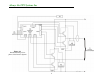
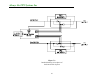
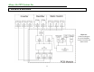
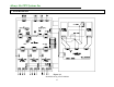
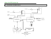
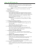
8. INTER-PCB
DIAGRAM
Figure 8.1
Connection diagram
for the PCB Module,
Inverter, Rectifier and
Static Switch
1
...
...
12
13
14
15
16
...
...
98