
Service manual

Always On UPS Systems Inc
56
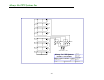
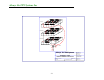
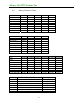
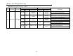
Table 19.1 LED Operation for the 3A PCB
NORMAL ABNORMAL
PCB FUNCTION LOCATION
PCB LED
LED
Illuminated
Description
LED
Illuminated
Description
SOLUTION
Check 3T (R phase) ensure cable connections
are secure and correctly attached.
LED A1 No
3T (R phase
working)
Yes
R phase failure
and UPS
shutdown
Replace the board
Check 3T (S phase) ensuring cable
connections are secure and correctly attached.
LED A2 No
3S (S phase
working)
Yes
S phase failure
and UPS
shutdown
Replace the board
Check 3T (T phase) ensuring cable
connections are secure and correctly attached.
LED A3 No
3T (T phase
working)
Yes
T phase failure
and UPS
shutdown
Replace the board
Check 3G and ensure cable connections are
secure and correctly attached.
LED A4 No 3G working Yes 3G has problem
Replace the board
Check 3B and ensure cable connections are
secure and correctly attached.
3A Main Control PCB Module
LED A5,
A6
All Yes PCB has power All No
PCB has no input
power
Replace the board