
Service manual


Always On UPS Systems Inc
58
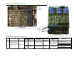
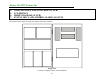
Table 20.1 LED Operation for the 3B PCB
NORMAL ABNORMAL
PCB FUNCTION LOCATION
PCB LED
LED
Illuminated
Description
LED
Illuminated
Description
SOLUTION
Check fuse set behind PCB
holder and ensure cable
connections are secure and
correctly attached.
LED B1,
B2, B3,
B4
All Yes PCB has power All No
All LED's of PCB
extinguished
Replace the board
LED B6 Yes
The system is testing
the batteries
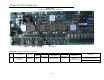
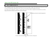
3B Power Supply PCB Module
LED B7 Yes
The system is boost
charging the batteries.
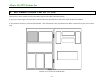
LED B2
LED B4
LED B1
LED B3
LED B7
LED B6
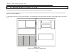
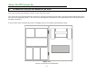
Picture 20.1
3B PCB
(
Power Su
pp
l
y)