
Service manual


Always On UPS Systems Inc
62
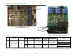
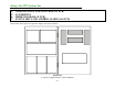
Table 22.1 LED Operation for the 3T PCB
NORMAL ABNORMAL
PCB FUNCTION LOCATION
PCB LED
LED
Illumination
Description
LED
Illumination
Description
SOLUTION
Ensure cable connections are secure
and correctly attached.
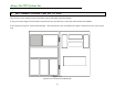
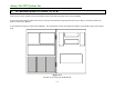
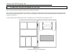
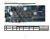
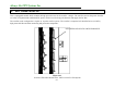
3T Inverter Phase Control PCB Module
LED T1,
T2
All Yes PCB has power All No
R, S or T phase lost,
output LED on the
front panel (mimic
diagram) blinks
indicating lost phase.
Replace the board
LED T1
LED T2
Picture 22.1
3T PCB
(Inverter Driver)