
Service manual


Always On UPS Systems Inc
73
Table 29.1 LED Operation for the 3G PCB
NORMAL ABNORMAL
PCB FUNCTION LOCATION
PCB LED
LED
Illumination
Description
LED
Illumination
Description
SOLUTION
Ensure cable connections are secure
and correctly attached.
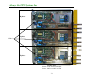
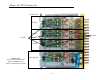
3G Inverter Driver (RST)
Inverter
Module
LED G1 Yes Inverter working No Inverter failure
Replace the board
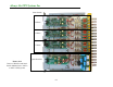
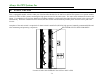
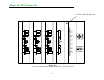
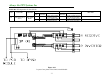
Figure 29.3
Layout of one phase of the Inverter Module