INSTALLATION INSTRUCTIONS DOUBLE O-RING GEOTHERMAL FLOW CENTERS Models: DORFC-1 DORFC-1 DORFC-2 DORFC-2 WARNING: After flushing is complete, but prior to pump motor start-up, loosen the large screw in the center of the pump motor(s) to allow air to escape. Once water has seeped out around the screw, re-tighten. Failure to perform this step will likely result in premature pump motor failure! PUMP MOTOR REPLACEMENT: Bard Part #8300-003 (UP26-99F) BMC, Inc.
Contents Getting Other Informations and Publications.......... 3 General Information Flow Center Nomenclature........................................ 4 Application Description................................................................. 4 Safety .................................................................. 4 Danger .................................................................. 4 Warning .................................................................. 4 Caution ................................
Getting Other Information and Publications These publications can help you install the air conditioner or heat pump. You can usually find these at your local library or purchase them directly from the publisher. Be sure to consult current edition of each standard.
geothermal flow centers nOMENCLATURE DORFC 2 Double O-Ring Flow Center 1 = 1-Pump Version, 208/230V, 60 Hz, 1-phase, 22’ HD @ 16 GPM 2 = 2-Pump Version, 208/230V, 60 Hz, 1-phase, 44’ HD @ 16 GPM fLow center description warning The DORFC Series Flow Centers are a compact, easy to mount polystyrene cabinet that contains 3-way valves and pump(s) with connections for flushing, filling and pumping fluids for geothermal closed loop systems.
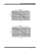
FLOW CENTER PERFORMANCE flow center performance FIGURE 1A PERFORMANCE MODEL DORFC-1 FLOW CENTER 35 30 20 15 10 5 0 0 5 10 15 20 25 30 35 Flow (GPM) FIGURE 1B PERFORMANCE MODEL DORFC-2 FLOW CENTER 70 60 50 Head (Feet) Head (Feet) 25 40 30 20 10 0 0 5 10 15 20 25 30 35 Flow (GPM) Manual 2100-518A Page 5 of 30 Manual 2100-518B Page 5 of 30
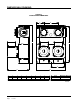
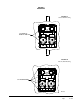
dimensional drawing figure 2 flow center dimensions F G A D H C INCHES CM A 13.5 34.3 B B 10.3 26.2 C 7.5 19.1 D 12.4 31.5 E 2.0 5.1 F 2.6 6.7 G 5.0 12.7 H 4.7 11.
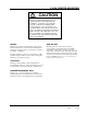
flow center mounting caution The following instructions represent industry accepted installation practices for closed-loop earth coupled (ground loop) installations. Instructions are provided to assist the contractor in installing trouble free ground loops. These instructions are recommendations only. State/provincial and local codes MUST be followed and installation MUST conform to ALL applicable codes.
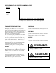
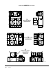
figure 3 pump horizontal applications OK IMPELLER SHAFT HORIZONTAL OK IMPELLER SHAFT HORIZONTAL NO IMPELLER SHAFT CAN NOT BE VERTICAL MIS-2659 Manual 2100-518B Page 8 of 30
figure 4 mounting FIGURE 4A Studded Wall Mounting 1/4" LAG BOLTS DIRECTLY INTO STUD FIGURE 4B Masonry Wall Mounting 1/4" TAPCON SCREWS MIS-2660 Manual 2100-518B Page 9 of 30
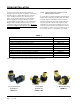
piping installation The Flow Center features Double O-Ring fittings for installation flexibility and ease of installation – maintaining a reliable connection. Table 1 illustrates the connection options available for Flow Centers. Pressure drop in piping systems should be calculated to ensure adequate flow through the unit. All piping should be properly insulated with closed cell insulation of 1/2" wall thickness.
piping installation (Continued) 1" Swivel X Double O-ring DORFP1-S Elbow, 1" MPT X Double O-ring with 1/4" Port and Pressure/Temperature Test Plugs DORMP1-90 1" Copper Sweat X Double O-ring with 1/4" FPT Port & Pressure/Temperature Test Plugs DORS1-S Elbow, 1" Hose Barb X Double O-ring with 1/4" Port and Pressure/ Temperature Test Plugs DORB1-90-4HC 1" Cam Lever Male X Double O-ring Garden Hose Male X O-ring (single) Adapter DORCL1-90 DORGHMT NOTES: 1. 2. 3.
figure 5A flow center connection to GV Series model PIPE TO GROUND LOOP PIPE FROM GROUND LOOP PUMP MODULE STRAIGHT BARBED BRASS ADAPTERS WATER IN WATER OUT HOSE CLAMPS NOTE: APPLY PETROLEUM JELLY TO O-RINGS TO PREVENT DAMAGE AND AID IN INSERTION. 1" FLEXIBLE HOSE multiple unit to single loop connection In instances where multiple units are connected to a singular loop, our recommendation is to apply a flow center to each individual system with full-port balancing valves installed on each unit.
figure 5B flow center connection to GT Series model PIPE FROM GOUND LOOP PIPE TO GROUND LOOP PUMP MODULE STRAIGHT BARBED BRASS ADAPTERS OPTIONAL VISUAL FLOW METER NOTE: IF USED SUPPORT WITH A FIELD FABRICATED WALL BRACKET HOSE CLAMPS 1" FLEXIBLE HOSE NOTE: APPLY PETROLEUM JELLY TO O-RINGS TO PREVENT DAMAGE AND AID IN INSERTION WATER OUT WATER IN MIS-2827 A Manual 2100-518B Page 13 of 30
figure 5C flow center connection to QW Series model FLEXIBLE HOSE PUMP MODULE (See Spec Sheet for Model No.
Manual 2100-518B Page 15 of 30 FIELD SUPPLIED FULL PORT BALL VALVE FOR BALANCING EACH HEAT PUMP FIELD SUPPLIED MUST INCLUDE P/T CHECK VALVE TO PORTS TO VERIFY PREVENT SHORT CYCLING FLOW RATES NOTES: 1. Piping is shown schematically. Actual pipe diameter and layout must be determined before installation. 2. Pressure drop calculation must be made to verify that parallel pumping arrangement provides enough head to deliver design flow rate to each unit when all units are operating. 3.
flow center wiring WARNING To avoid possible injury or death due to electrical shock, open the power supply disconnect switch and secure it in an open position during installation. caution Use only copper conductors for field installed electrical wiring. Unit terminals are not designed to accept other types of conductors. Power wiring to the Flow Center should conform to all applicable codes. Figure 7 shows the required wiring between the geothermal heat pump and the flow center.
figure 7 electrical connections FLOW CENTER ELECTRICAL ENTRANCE FLOW CENTER CONNECTION L1 L2 38 Red 37 Black Circuit Breakers PUSH 3 MIS-2665 PUSH 3 Terminal Block 2 Manual 2100-518B Page 17 of 30
flushing & charging All Flushing of earth loops should be performed using a 1.5 HP or larger pump (as specified by IGSHPA). Flushing can be accomplished using three different methods. The first flushing method applies a one-step installation of the loop, unit and inside piping. The second method allows a Loop Contractor to use flush cart when installing the loop, and at a later date, the dealer can install the unit to the loop using only domestic water to flush the unit.
flushing & charging (Continued) figure 8 connecting flush cart to flow center RETURN SUPPLY MIS-2661 Manual 2100-518B Page 19 of 30
flushing & charging (Continued) figures 9A & 9B flow center valve positioning FLUSH LOOP ONLY FLUSH LOOP & UNIT TOGETHER MIS-2662 Manual 2100-518B Page 20 of 30
flushing & charging (Continued) figures 9C & 9D flow center valve positioning FLUSH UNIT ONLY OPERATION MIS-2663 Manual 2100-518B Page 21 of 30
flushing & charging (continued) flushing & filling earth loop and unit(s) together flushing earth loop only All air and debris must be removed from the earth loop piping system before operation. Flush the loop with a high volume of water at a high velocity (2 fps in all piping in accordance with IGSHPA guidelines). 2. Connect the unit side connections of the flow center together with a jumper hose. 1. Connect the unit and loop to the flow center. 2.
flushing & charging (continued) flushing unit only (Also used when replacing unit, coaxial coil, hose kit or pump) 1. Connect unit to flow center. 2. Rotate 3-way valve to position shown in Figure 9C. 3. Remove access port caps and plugs and connect either flush cart or Bard DORGHMT fitting (service only not intended for primary flush). 4. Attach garden hose to domestic water supply. 5. Purge air from garden hose before connecting to port in flow center. 6.
flow center initial startup 1. Check to make sure the loop and unit isolation valves are completely open and the flush ports are closed and sealed (see Figure 9D). 2. Geothermal units have two low pressure switches installed. One switch is intended for Ground Water Applications (default factory wired - blue wires), and the second is intended for Ground Loop Applications (yellow wires).
figure 10 pressure temperature ports Thermometer NOTE: Slide retaining cap back to expose double o-rings. Apply petroleum jelly to o-rings to prevent damage and aid in insertion Dial face pressure guage with guage adaptor 40 50 60 70 Retaining cap, hand tighten only 80 30 90 20 100 10 110 0 120 P/T test plug Pete's Test plug cap Barbed 90° adapter MIS-2622 A TABLE 3A GV Series coil pressure drop Model GV27S1 GPM PSID Ft. Hd. 3 0.1 0.23 4 0.5 5 GV38S1 / GV51S1 PSID Ft. Hd. 1.
TABLE 3B GT Series coil pressure drop Model GTC48S1 GTC36S1 GPM PSID Ft. Hd. PSID Ft. Hd. 3 0.1 0.23 4 0.5 1.15 0.9 2.08 5 1.2 2.77 1.4 3.23 6 1.7 3.92 2.3 5.31 7 2.3 5.31 3.2 8 3.1 7.15 9 4.1 9.46 GTC60S1 PSID Ft. Hd. 7.38 2 4.61 4.1 9.46 2.5 5.77 5.1 11.77 3.2 7.38 10 6.1 14.07 3.9 9.00 11 7.1 16.38 4.7 10.84 12 8.2 18.92 5.5 12.69 13 9.4 21.69 6.4 14.76 14 10.6 24.45 7.3 16.84 15 8.1 18.69 16 9 20.76 17 9.9 22.
troubleshooting Problem Water Drips Out Low Flow / No Flow Noisey Pressure Loss Unit Trips Out on Water Flow (Low Pressure or High Pressure) Possible Causes Checks & Corrections Condensation Insulate piping, check for insulation gaps. Water Leak Inspect/tighten fittings. Power Loss Check power supply from the heat pump. Blown Circuit Breaker Reset circuit breaker for flow center in heat pump control box. Broken or Loose Wires Replace or tighten wires.
ANTIfreeze selection & use Selection of antifreeze solutions for ground loop applications requires consideration of many important factors, which may have long-term implications in regards to performance and system component life. Each area of concern leads to a different antifreeze solution. The fact that there is no “ideal” antifreeze and any choice will require compromises in one area or another.
ANTIfreeze selection & use (continued) Potassium Acetate (GS4) – Non-toxic, good heat transfer, high price, non-corrosive with added inhibitors, low viscosity. Due to its low surface tension, Potassium Acetate has been known to leak through mechanical fittings and certain thread sealants. A variant of the salt family, it can be extremely corrosive when exposed to air. Potassium Acetate is not recommended in ground loop applications due to the leaking and (ultimately) corrosion problems associated with it.
WARNING WARNING Always use properly marked vehicles (D.O.T. Always use properly marked vehicles (D.O.T. placards) and clean/suitable/properly marked placards) containers and clean/suitable/properly marked identified for handling flammable identified containers handling flammable antifreeze mixtures. for Post and advise those antifreeze mixtures. Post and those on the jobsite of chemical use advise and potential on the jobsite of chemical use and potential dangers of handling and storage.