USB & eSATA combo RAID Enclosure Storage Appliance AES-S3504UE User’s Manual October 15, 2009
Table of Contents 1 WELCOME........................................................................................................................................................4 1.1 1.2 1.3 1.3.1 1.3.2 1.3.3 1.4 1.5 1.5.1 1.5.2 1.6 2 STORAGE POLICIES......................................................................................................................................9 2.1.1 2.1.2 2.1.3 2.1.4 2.1.5 2.1.6 2.1.7 2.1.8 3 CLEAN MODE..........................................................
4.3.2 MACINTOSH SYSTEMS...........................................................................................................................32 4.4 HARD DISK DRIVE HOT-PLUG & HOT-UNPLUG...............................................................................32 4.5 LED INDICATIVE STATUS.......................................................................................................................32 4.5.1 POWER LED..............................................................................
1 WELCOME 1.1 INTRODUCTION Thank you for choosing AES-S3504UE storage appliance. It is a low-cost solution for digital home and small office storage appliances. Features of the AES-S3504UE include advanced RAID modes. It’s available from leading storage partners in pre-configured set-ups with USB or eSATA host connections.
1.2 PRECAUTION Please read the safe precautions carefully before you using AES-S3504UE storage appliance. Ensure that you use the product correctly according to the procedure described in this guide. The following safety precautions are intended to remind you to operate the product safely and correctly. Please read and ensure that you understand them before you proceed to the other sections of this guide. Do not plug any HDD(s) while power is on (except operation in CLEAN MODE).
1 host port (eSATA or USB) to 4 Serial ATA hard disk drives. Compatible with SATA Gen1 and Gen2 host controllers. Compatible USB 2.0 specifications. Embedded fast Storage Processor. Ultra-fast 3Gbps host and device port capability. Greater than 200MBps sustained reads in R0 mode (limited by drives and host controller). 1.3.2 SATA FEATURES The AES-S3504UE provides the following Serial Advanced Technology Attachment (SATA) features: 1 eSATA host port to 4 SATA devices (Port Multiplier Functionality).
265 (L) x 135 (W) x 186 (H) mm, NW: 2.4 Kgs, GW: 3.5Kgs. 150 watts power supply, 100 to 132Vac or 200 to 264Vac select switch / 47~63Hz with CE/ FCC/ UL/ CB/ BSMI requirement. Physical Dimensions: 121 mm (L) x 72 mm (W) x 35 mm (H). Single packing (color box) and 4 in 1 outer carton. 1.5 SYSTEM REQUIREMENTS 1.5.
• Mac OS Snow Leopard 10.6.x • CD-ROM drive • Mouse or compatible pointing device • SATA connection: Optional Host Bus Adapter card (controller number Sii3132) and associated software drivers with Port Multiplier support • USB connection: USB 1.0 or 2.0 direct host connection or USB hub 1.6 PRODUCT CONTENTS The following parts are content. AES-S3504UE x 1. Tool-less Screw x 8. USB 2.0 Cable x 1. Setup and Installation Driver Repository CD x 1. eSATA Cable x 1. SATA to eSATA Bracket Cable x 1.
2 STORAGE POLICIES You can configure the AES-S3504UE storage appliance to use any of the following storage policies to map the appliance’s physical hard drives to virtual drives that are visible to the host computer. The virtual drives are called volumes. The host operating system treats each volume as if it were a single physical drive. This virtualization allows you to overcome restrictions that are imposed by physical hard drives, such as speed, storage capacity or data storage reliability. 2.1.
It is also possible to create a LARGE volume using only a single hard disk drive connected to Port 1. However, it is not possible to expand an existing LARGE volume by adding another hard disk drive and still preserve any existing data on that volume. 2.1.3 CLONE MODE The CLONE MODE storage policy stores all data in duplicate on separate drives to protect against data loss due to drive failure. One drive clones the others at all times. Every write operation goes to all drives.
2.1.4 R0 MODE The R0 MODE storage policy distributes access across all hard disks. R0 MODE presents the best data speed but no data redundancy. R0 MODE storage policy accelerates hard disk drive operating speed by using many disks in parallel. Hard disk drive data segments are written to different disks simultaneously which increases performance while sacrificing data redundancy.
access takes precedence over the rebuild process. If you continue to use the R1 volume during the rebuild, the rebuild process will take a longer time to complete, and the host data transfer performance will also be affected. 2.1.6 R10 MODE The R10 MODE storage policy combines the features of both R0 and R1. Performance is provided through the use of R0 MODE, while adding the fault tolerance of R1. The implementation of R10 requires four drives. The drives are assigned as two sets of striped pairs.
drive. There are at least 3 members to a virtual R3 volume. The following example illustrates how the parity is rotated from drive to drive. The R3 MODE uses less capacity for protection and is the preferred method to reduce the cost per megabyte for larger installations. In exchange for low overhead necessary to implement protection, the R3 MODE degrades performance for all write operations.
The R5 MODE uses less capacity for protection and is the preferred method to reduce the cost per megabyte for larger installations. In exchange for low overhead necessary to implement protection, the R5 MODE degrades performance for all write operations. The parity calculations for R5 MODE may result in write performance that is somewhat slower than the write performance to a single drive. The resulting storage capacity of the virtual R5 volume will be four times of the smallest drive.
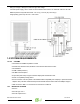
3 INSTALLATION 3.1 BEFORE INSTALLATION Please unplug the power cable, and switch the VAC to the correct position (For example, 115 for Japan, and 230 for UK) before installing. It may exposure to strong magnetic fields and malfunctions or damage. 3.2 INSTALLING HARD DISK DRIVE Please refer below procedure to complete the HDD installation. • Unfasten the Tool-less screws on the back panel. • Remove the upper chassis cover backwards and lifts it up. AES-S3504UE User’s Manual Ver.
• Open the front door and install the HDDs in order from the top to the bottom. Please refer to the diagram. • Twist the tool-less screw shut to seat the drive securely. • Close the front door and the upper chassis cover, than fasten the tool-less screws on the back panel. 3.3 UNSTALLING HARD DISK DRIVE Please unfasten the tool-less screw, and release the HDD from the 22-pin SATA connector by use the tool-less screw, than remove the HDD one by one securely. Ver.
3.4 POWER ON / OFF • Push power switch to “ - “ position to power on. • Push power switch to “ O “ position to power off. 3.5 INSTALLING SATA TO ESATA BRACKET CABLE • Remove a free I/O bracket from your computer. • Install the SATA TO ESATA BRACKET CABLE to the free I/O bracket, and connect the SATA cable to a free SATA port from your computer. AES-S3504UE User’s Manual Ver.
3.6 INSTALLING HOST BUS ADAPTER (OPTIONAL) 3.6.1 WINDOWS XP (32/64-bit) 1. Select No, not this time, than click Next. 2. Select Install the software automatically (Recommended), than click Next. Ver.
3. Click Finish to complete installation. 3.6.2 WINDOWS VISTA (32/64-bit) 1. Click Locate and install driver software (recommended). AES-S3504UE User’s Manual Ver.
2. Click Next for next step. 3. Click Close to complete installation. Ver.
3.6.3 WINDOWS 7 RC2 (32-bit) 1. Go to the Device Manager. 2. Right click on the Mass Storage Controller, than Select Update Driver Software. AES-S3504UE User’s Manual Ver.
3. Click Browse my computer for driver software. 4. Browse to select the 32bits folder from the Repository CD to begin the installation (Located at: E:\Driver\SiI3132\Windows\32bits PS: "E:" = CD-ROM drive letter). Ver.
5. Click Finish to complete installation. 3.6.4 WINDOWS 7 RC2 (64-bit) 1. Go to the Device Manager. AES-S3504UE User’s Manual Ver.
2. Right click on the Mass Storage Controller, than Select Update Driver Software. 3. Click Browse my computer for driver software. Ver.
4. Browse to select the 64bits folder from the Repository CD to begin the installation (Located at: E:\Driver\SiI3132\Windows\64bits PS: "E:" = CD-ROM drive letter). 5. Click Finish to complete installation. AES-S3504UE User’s Manual Ver.
3.6.5 MACINTOSH OS TIGER 10.4.X / LEOPARD 10.5.X / SNOW LEOPARD 10.6.X 1. Insert the Setup and Installation Repository Driver CD in the CD-ROM drive. 2. Double-click on the Setup and Installation Repository Driver CD icon. 3. Double-click the 3132-Mac.pkg file to begin the installation (Located at: E:\Driver\SiI3132\Macintosh\3132-Mac.pkg PS: "E:" = CD-ROM drive letter). Ver.
4. Once started, the following dialog screens will appear, Click Continue. 5. Read the Read Me file, than click Continue. AES-S3504UE User’s Manual Ver.
6. Read the Software License Agreement, than click Continue. 7. Click Agree to continue the installation. Ver.
8. Select a destination volume to install the software, than click Continue. 9. Click Install to begin the installation. AES-S3504UE User’s Manual Ver.
10. Enter the Administrative Password for your system, than click OK. 11. Click Close to complete the installation. Ver.
4 CONFIGURATION 4.1 CONFIGURATION PREREQUISITES 4.1.1 SATA HOST CONNECTIONS This guide assumes that you have already attached the AES-S3504UE to a host computer that has been installed with the Sii3132 HBA (Host Bridge Adapter) or another third party SATA HBA with Port Multiplier (PM) support. If you use a host controller that does not provide Port Multiplier support (Such as Intel ICH): • The CLEAN MODE storage policy is unavailable when configuring the AES-S3504UE.
2. A message will appear listing all of the devices that the Eject icon controls. Click on the “Safely remove USB Mass Storage Device” item. 3. The following message then appears: “Safe to Remove Hardware”. You can now safely disconnect the device from your computer. Note: If your host USB adapter does not support this feature, the device should be disabled using the Device Manager or your system should be shut down cleanly and powered off before disconnecting the USB device. 4.3.
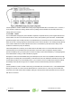
4.5.1 POWER LED The AES-S3504UE has one Amber color Power LED. The table shows Power LED function and operation. DESCRIPTION Power On GREEN LED On Power Off 4.5.2 Off PC LINK LED The AES-S3504UE has one Green color PC Host Link LED. The table shows PC Link LED function and operation. DESCRIPTION PC Link Unplugged / No Power GREEN LED Off PC Link plugged (Idle) On PC Link plugged (Active) On 4.5.3 HRAD DISK DRIVE LED The AES-S3504UE has five HDD LEDs (Green and Red) on the front panel.
4.6 MODE SETTING The AES-S3504UE with the device’s LEDs to indicate status. To select a storage policy in this mode the first time that a new factory-shipped product is used, ensure that the hard disk drives are installed; turn off the power before set the MODE SWITCH on the back of the AES-S3504UE to the desired Storage Policy. To change the storage policy thereafter, set the MODE SWITCH to the desired position and press and hold the recessed SETUP BUTTON, than power on to create the new virtual volume(s).
4. Turn on the power than release the SETUP BUTTON to complete mode setting. 4.6.2 LARGE MODE The LARGE MODE storage policy requires a minimum of 2 drives to implement. 1. Turn off the power. 2. Set the MODE SWITCH position to LARGE. 3. Press and hold the recessed SETUP BUTTON. AES-S3504UE User’s Manual Ver.
4. Turn on the power than release the SETUP BUTTON to complete mode setting. 4.6.3 CLONE MODE The CLONE MODE storage policy requires a minimum of 2 drives to implement. 1. Turn off the power. 2. Set the MODE SWITCH position to CLONE. 3. Press and hold the recessed SETUP BUTTON. Ver.
4. Turn on the power than release the SETUP BUTTON to complete mode setting. 4.6.4 CLONE MODE WITH HOT SPARE The CLONE MODE storage policy with hotspare drive requires a minimum of 3 drives to implement. 1. Turn off the power. 2. Insert 2 drives in order from the top to the bottom. 3. Set the MODE SWITCH position to CLONE. AES-S3504UE User’s Manual Ver.
4. Press and hold the recessed SETUP BUTTON. 5. Turn on the power than release the SETUP BUTTON. 6. Turn off the power. rd 7. Insert the hotspare drive into the 3 HDD bay. Ver.
8. Turn on the power to complete mode setting. 4.6.5 R0 MODE The R0 MODE storage policy requires a minimum of 2 drives to implement. 1. Turn off the power. 2. Set the MODE SWITCH position to R0. 3. Press and hold the recessed SETUP BUTTON. AES-S3504UE User’s Manual Ver.
4. Turn on the power than release the SETUP BUTTON to complete mode setting. 4.6.6 R1 MODE The R1 MODE storage policy requires 2 drives to implement. 1. Turn off the power. 2. Set the MODE SWITCH position to R1/R10. 3. Press and hold the recessed SETUP BUTTON. Ver.
4. Turn on the power than release the SETUP BUTTON to complete mode setting. 4.6.7 R1 MODE WITH HOT SPARE 1. Turn off the power. 2. Insert 3 drives in order from the top to the bottom. 3. Set the MODE SWITCH position to R1/R10. AES-S3504UE User’s Manual Ver.
4. Press and hold the recessed SETUP BUTTON. 5. Turn on the power than release the SETUP BUTTON to complete mode setting. 4.6.8 R10 MODE The R10 MODE storage policy requires 4 drives to implement. 1. Turn off the power. 2. Set the MODE SWITCH position to R1/R10. Ver.
3. Press and hold the recessed SETUP BUTTON. 4. Turn on the power than release the SETUP BUTTON to complete mode setting. 4.6.9 R3 MODE The R3 MODE storage policy requires a minimum of 3 drives to implement. 1. Turn off the power. 2. Set the MODE SWITCH position to R3. AES-S3504UE User’s Manual Ver.
3. Press and hold the recessed SETUP BUTTON. 4. Turn on the power than release the SETUP BUTTON to complete mode setting. 4.6.10 R3 MODE WITH HOT SPARE The R3 MODE storage policy with hotspare drive requires a minimum of 4 drives to implement. 1. Turn off the power. 2. Insert 3 drives in order from the top to the bottom. Ver.
3. Set the MODE SWITCH position to R3. 4. Press and hold the recessed SETUP BUTTON. 5. Turn on the power than release the SETUP BUTTON. 6. Turn off the power. AES-S3504UE User’s Manual Ver.
th 7. Insert the hotspare drive into the 4 HDD bay. 8. Turn on the power to complete mode setting. 4.6.11 R5 MODE The R5 MODE storage policy requires a minimum of 3 drives to implement. 1. Turn off the power. 2. Set the MODE SWITCH position to R5. Ver.
3. Press and hold the recessed SETUP BUTTON. 4. Turn on the power than release the SETUP BUTTON to complete mode setting. 4.6.12 R5 MODE WITH HOT SPARE The R5 MODE storage policy with hotspare drive requires a minimum of 4 drives to implement. 1. Turn off the power. 2. Insert 3 drives in order from the top to the bottom. AES-S3504UE User’s Manual Ver.
3. Set the MODE SWITCH position to R5. 4. Press and hold the recessed SETUP BUTTON. 5. Turn on the power than release the SETUP BUTTON. 6. Turn off the power. Ver.
th 7. Insert the hotspare drive into the 4 HDD bay. 8. Turn on the power to complete mode setting. 4.7 REBUILDING A REDUNDANCY OR HOT SPARE DRIVE The AES-S3504UE storage appliance stores all data in duplicate on separate drives to protect against data loss due to drive failure on CLONE, R1, R3, R5, and R10 MODE. The following example illustrates how the procedure to rebuilding a redundancy or hot spare drive. 4.7.1 REBUILDING A REDUNDANCY DRIVE 1.
2. Turn off the power. 3. Replace a same or larger size of hard disk drive. 4. Turn on the power. 5. The AES-S3504UE storage appliance will rebuild the virtual volume from degrade mode to normal automatically (Approximately 200GB/hour). Ver.
4.7.2 REBUILDING A HOT SPARE DRIVE 1. If the there is a hot spare drive on drive 4, and the drive 2 has breakdown, the hot spare drive on drive 4 will replace the breakdown drive and rebuild automatically.To setup a new hot spare drive, please remove the breakdown drive 2. 2. Turn off the power. 3. Replace a same or larger size hard disk drive. 4. Turn on the power. 5. The AES-S3504UE storage appliance will replace a hot spare drive on drive 2 automatically. AES-S3504UE User’s Manual Ver.
5 PARTITIONING VOLUMES 5.1 PARTITION A VOLUME 5.1.1 WINDOWS SYSTEMS Note: Before repartition a volume, back up your data and delete previously defined partitions. 1. Right-click the My Computer icon on your desktop and select Manage from the pop-up window. 2. Select Disk Management under Storage to open the Windows Disk Manager. This example illustrates the LARGE storage policy, which concatenates the capacity of all hard drives connected to the TERA BOX SATA RAID III.
opens with the selected disk (all Unknown disks may appear in this window). Make sure the box next to each disk is checked and click OK. The disk should now be marked as a Basic disk. If a disk appears as “Dynamic”, right-click the disk icon, and select Revert to Basic Disk. Within a few seconds, the disk should be marked as a Basic disk. If a disk is marked “Not Initialized”, right-click the disk icon and select Initialize Disk.
4. Click Next to start the Partition Wizard. 5. Select the Primary or Extended option and click Next. Ver.
6. Specify the partition size. By default, the partition occupies the entire volume. Click Next. 7. Assign a drive letter or mount path and click Next. AES-S3504UE User’s Manual Ver.
8. Name and format the partition and click Next. 9. Review the file system settings and click Finish to create the logical partition. Ver.
10. Repeat steps 1 through 9 to partition any remaining disks. 5.1.2 MACINTOSH SYSTEMS Note: Before reconfiguring a volume, back up your data and drag the old drive to the trash to unmount previously partition. After you configure and partition the new volumes, restore the backed-up data to the new configuration. 1. Launch Disk Utility from the Application > Utilities folder. AES-S3504UE User’s Manual Ver.
2. Select a configured disk and click the Partition tab. This procedure illustrates the LARGE Storage Policy configuration, which concatenates the capacity of all hard drives connected to the TERA BOX SATA RAID III. 3. Select 1 Partition from the Volume Scheme drop-down list. 4. Enter a name for the volume in the Name field (such as “My Disk”.) 5. Select Mac OS Extended (journaled) from the Format drop-down list. 6. Specify the size of the partition in the Size field. 7. Click the Partition button. 8.
Disk Utility mounts the created partition and represents it with an icon on the desktop. The icon is labeled with the partition name. 9. Repeat steps 1 through 8 to partition any remaining disks you configured. AES-S3504UE User’s Manual Ver.
6 APPENDIX 6.1 FAQ If you need some help for troubleshooting, please check the frequently asked question below, it may help you problem solved quickly Can not recognize .Make sure all cables have been connected properly. Can not operate in O/S .Make sure the O/S is support for the product. Transmission speed is slow .If connect USB1.1 interface, the speed will be around 1MB/sec only.
Manufacturer Capacity Family Part Number Firmware Hitachi 250GB Deskstar™ 7K250 HTS54252K9SA00 BBFOC31P Hitachi 160GB Deskstar™ 7K80 HDS72180PLA380 P22OABEA Hitachi 160GB Deskstar™ 7K160 HDS721616PLAT80 P22OABEA Hitachi 80GB Deskstar™ 7K160 HDS721680PLA380 P210A70A Hitachi 80GB Travelstar ™ 5K100 HTS541080G9SA00 MB40C60R Hitachi 80GB N/A Hitachi 2.
Manufacturer Capacity Family Seagate 160GB Part Number Firmware Barracuda® 7200.7 Serial ATA ST3160827AS 3.42 Seagate 160GB SV35 ST3160812SV 3.ALP Seagate 80GB Momentus® 5400.3 SATA ST980811AS 3.ALC Seagate 80GB DiamondMax® 10 6V080E0 3.AAD Seagate 60GB Momentus® 5400.2 ST96812AS 3.06 Seagate 2.5” 120GB N/A ST9120822AS 3.ALC Toshiba 2.5” 320GB N/A MK3252GSX LV010D Toshiba 2.5” 250GB N/A MK2546GSX LB012D Toshiba 2.5” 160GB N/A MK1637GSX DL050J Toshiba SSD 2.
6.3 MOTHERBOARD COMPATIBILITY LIST The AES-S3504UE Storage Appliance has been tested compatibility with a range of motherboard manufacturer. The table is updated as new motherboards are certified for compatibility. Only motherboards included in this table are supported. Manufacturer Product North Bridge South ABIT VIA P4M890 IP-95 V1.
Manufacturer Product North Bridge South Bridge BIOS GIGABYTE GA-73PVM-S2H NVIDIA GEFORCE 7100 MCP73 F7A GIGABYTE GA-M78SM-S2H NVIDIA GEFORCE 8200 NVIDIA GEFORCE 8200 F1 MSI K9AG NEO2-DIGITAL AMD 690G ATI SB600 N/I MSI P35D3 PLATINUM INTEL P35 INTEL ICH9R V1.062807 MSI K8N-NEO4H NVIDIA NFORCE4 ULTRA NFORCE4 V7.