
Service manual


SERVICING
108
S-16G CHECKING EMERSON ULTRATECH
TM
ECM
MOTORS
DESCRIPTION
The AVPTC and MBVC models utilize an Emerson, 4-wire
variable speed ECM blower motor. The ECM blower motor
provides constant CFM.
The motor is a serially communicating variable speed motor.
Only four wires are required to control the motor: +Vdc,
Common, Receive, and Transmit.
The +Vdc and Common wires provide power to the motor's
low voltage control circuits. Typical supply voltage is 9-15
volts DC.
GENERAL CHECKS/CONSIDERATIONS
1. Check power supply to the air handler or modular blower.
Ensure power supply is within the range specified on
rating plate. See section S-1.
2. Check motor power harness. Ensure wires are continu-
ous and make good contact when seated in the connec-
tors. Repair or replace as needed.
3. Check motor control harness. Ensure wires are continu-
ous and make good contact when seated in the connec-
tors. Repair or replace as needed.
4. Check thermostat and thermostat wiring. Ensure thermo-
stat is providing proper cooling/heating/continuous fan
demands. Repair or replace as needed.
5. Check blower wheel. Confirm wheel is properly seated on
motor shaft. Set screw must be on shaft flat and torqued
to 165 in-lbs minimum. Confirm wheel has no broken or
loose blades. Repair or replace as needed.
6. Ensure motor and wheel turn freely. Check for interfer-
ence between wheel and housing or wheel and motor.
Repair or replace as needed.
7. Check housing for cracks and/or corrosion. Repair or
replace as needed.
8. Check motor mounting bracket. Ensure mouting bracket
is tightly secured to the housing. Ensure bracket is not
cracked or broken.
Emerson UltraCheck-EZ
TM
Diagnostic Tool
The Emerson UltraCheck-EZ
TM
diaganostic tool may be used
to diagnose the ECM motor.
HIGH VOLTAGE!
Disconnect ALL power before servicing
or installing. Multiple power sources
may be present. Failure to do so may
cause property damage, personal injury
or death.
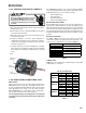
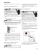
To use the diagnostic tool, perform the following steps:
1. Disconnect power to the air handler.
2. Disconnect the 4-circuit control harness from the motor.
3. Plug the 4-circuit connector from the diagnostic tool into
the motor control connector.
4. Connect one alligator clip from the diagnostic tool to a
ground source.
5. Connect the other alligator clip to a 24VAC source.
NOTE: The alligator clips are NOT polarized.
NOTE: The UltraCheck-EZ
TM
diagnostic tool is equipped
with a nonreplaceable fuse. Connecting the tool to a source
other than 24VAC could damage the tool and cause the fuse
to open. Doing so will render the diagnostic tool inoperable.
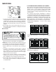
6. Turn on power to air handler or modular blower.
WARNING
Line Voltage now present.
7. Depress the orange power button on the diagnostic tool
to send a run signal to the motor. Allow up to 5 seconds
for the motor to start.
NOTE: If the orange power button does not illuminate when
depressed, the tool either has an open fuse or is not properly
connected to a 24VAC source.
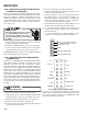
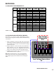
8. The green LED on the diagnostic tool will blink indicating
communications between the tool and motor. See table
below for indications of tool indicators and motor actions.
Replace or repair as needed.
Power
Button
Green
LED
Motor
Action
Indication(s)
OFF OFF
Not
Rotating
Confirm 24VAC to
UltraCheck-EZ
TM
tool.
If 24VAC is confirmed,
diagnostic tool is
inoperable.
ON Blinking Rotating
Motor and control/end
bell are functioning
properly.
ON OFF Rotating
Replace motor
control/end bell.
ON Blinking
Not
Rotating
Check motor (see
Motor Check s below).
ON OFF
Not
Rotating
Replace motor
control/end bell; verify
motor (see Motor
Checks below).
9. Depress the orange power button to turn off motor.
10. Disconnect power. Disconnect diagnostic tool.