
Service manual


SERVICING
112
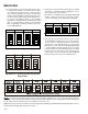
NOTE: When 8kW and 10kW heat kits are used with an
AVPTC1830 and AVPTC313, matched with 2-ton outdoor
unit, see Note 1below.
1 Set Heater Kit dip switches 9, 10 and 11 to 6kW setting
(9-ON, 10-OFF, 11-ON) to obtain 840 CFM.
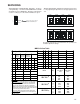
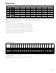
AVPTC Airflow Table
Profiles 5 6
AOFFOFF
BONOFF
COFFON
DONON
30 sec/50% 7.5 mins/82% 30 sec/50%
------- 30 sec/50% 60 sec/100%
------- 7.5 mins/82% 60 sec/100%
Profile
Sel ect io n
Switches
Pre-Run Short-Run Off Delay
------- ------- 60 sec/100%
Tap 1 2
TRIM
34
AOFFOFF
0%
OFF OFF
BONOFF
+ 10%
ON OFF
COFFON
- 10%
OFF ON
DONON
0%
ON ON
Adjust
Selection
Switches
Cool
Selection
Switches
Speed Selection Dip Switches
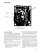
TO SET AIRFLOW:
1.Select appropriate model from Cooling/Heat Pump Airflow Table.
Based on desired Airflow for your application select corresponding tap
(A,B,C or D). Set dip switches 1 & 2 to the appropriate ON/OFF
positio ns.
2. Select appropriate Airflow adjustment factor for application
(0%. +10%, -10%). Set dip switches 3 & 4 to the appropriate ON/OFF
positio ns.
3. If installed with Heater Kit:
Using Electric Heat Airflow Table, set dip switches 9, 10 and 11 to the
appropriate ON/OFF positions based on Heater kit installed.
If installed without Heater Kit:
Ensure dip switches 9, 10 and 11 are set to a valid heater kit selection.
Example: The only valid heater kits for AVPTC183014* applications
are 3, 5, 6, 8 and 10 kW.
Failure to do so will result in a Heater Kit error code.
TO SET COMFORT MODE:
Select desired Comfort Mode profile (see profiles above). Set switches
5 and 6 to the appropriate ON/OFF positions.
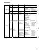
Tap
Low
Stage
Cool
High
Stage
Cool
A 420 630
B 560 840
C 700 1040
A 410 610
B 560 830
C 700 1040
D 830 1240
A 810 1210
B 940 1410
C 1050 1560
D 1210 1800
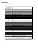
Htr kW 9 10 11
AVPTC
183014*
AVPTC
313714*
AVPTC
426014*
3 ONONON630610600
5 ON ON OFF 730 710 680
6 ON OFF ON 840 840 790
8 ON OFF OFF 1080 1060 990
10 OFF ON ON 1270 1260 1190
15 OFF ON OFF NR 1470 1390
20 OFF OFF ON NR NR 1580
21 OFF OFF OFF NR NR 1580
NOTE: Airflow data sho wn applies to the emergency hea t m ode ( electric heat only) in either non-
communicatin g mode operation or fully communicating mode o peration.
Cooling/Heat Pump Airflow Table
Electr ic Heat Airflow T able
NOTE: Airflow data sho wn applies to non-communicating mode operation only. For a fully
communicating system, please see the outdoor unit's install ation instructions for cooling and heat
pump airflow data.
See Comfor tNet™ System - Airflow Conside ration section for details.
Model
AVPTC183014*
AVPTC313714*
AVPTC426014*