
Service manual


SERVICING
115
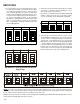
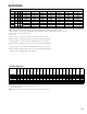
• Profile A provides only an OFF delay of one (1) minute
at 100% of the cooling demand airflow.
OFF
100% CFM 100% CFM
1 min
OFF
• Profile B ramps up to full cooling demand airflow by first
stepping up to 50% of the full demand for 30 seconds.
The motor then ramps to 100% of the required airflow.
A one (1) minute OFF delay at 100% of the cooling
airflow.
50% CFM
1/2 min
100% CFM
100% CFM
1 min
OFF
OFF
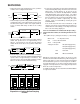
• Profile C ramps up to 82% of the full cooling demand
airflow and operates there for approximately 7 1/2
minutes. The motor then steps up to the full demand
airflow. Profile C also has a one (1) minute 100% OFF
delay.
100% CFM
OFF
OFF
• Profile D ramps up to 50% of the demand for 1/2 minute,
then ramps to 82% of the full cooling demand airflow and
operates there for approximately 7 1/2 minutes. The
motor then steps up to the full demand airflow. Profile
D has a 1/2 minute at 50% airflow OFF delay.
OFF
OFF
S5
S6
S5
S6
S5
S6
S5
S6
OFF OFF OFF OFFON ON ON ON
Tap A* Tap B Tap C Tap D
Dipswitches - Cooling Airflow Ramping
Profiles
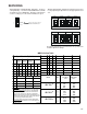
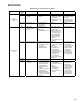
7. If an electric heater kit has been installed, determine the
heater kilowatt (kW) rating. Find the heater size in the
table below. Set dip switches 9, 10, and 11 for the
installed heater as shown in the Dipswitches - Electric
Heat Airflow table on the previous page. The adjust
setting (already established by the cooling speed selec-
tion) also applies to the electric heater kit airflow. Thus,
the electric heater airflow is adjusted by the same
amount. Verify selected CFM by counting the green
CFM LED blinks.
If an electric heater kit has not been installed, set dip
switches 9, 10, and 11 to any valid heater kit setting (see
ariflow table for valid settings). This will prevent an Ec
Error code from being displayed.
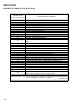
NOTE: For installations not indicated in the preceding
Temperature Rise Tables, the following formula is to be
used:
TR = (kW x 3412) x (Voltage Correction) x (1.08 x CFM)
Where: TR = Temperature Rise
kW = Heater Kit Actual kW
3412 = Btu per kW
Voltage Correction =.96 (230 Supply Volts)
=.92 (220 Supply Volts)
=.87 (208 Supply Volts)
1.08 = Constant
CFM = Measured Airflow
NOTE: The Temperature Rise Tables can also be used to
determine the air handler airflow delivery. When using these
tables for this purpose set the room thermostat to maximum
heat and allow the system to reach steady state conditions.
Insert two thermometers, one in the return air and one in the
supply air. The temperature rise is the supply air temperature
minus the room air temperature.
Use HKR specification sheets to determine the HKR available
for a given air handler.