
Service manual

SERVICING
129
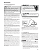
During a cooling or heat pump heating demand, 24Vac is
supplied to terminal “G” of the EBTDR to turn on the blower
motor. The EBTDR initiates a 7 second delay on and then
energizes it’s onboard relay. The relay on the EBTDR board
closes it’s normally open contacts and supplies power to the
blower motor. When the “G” input is removed, the EBTDR
initiates a 65 second delay off. When the 65 seconds delay
expires the onboard relay is de-energized and it’s contacts
open and remove power from the blower motor.
During an electric heat only demand, “W1” is energized but
“G” is not. The blower motor is connected to the normally
closed contacts of the relay on the EBTDR board. The other
side of this set of contacts is connected to the heat sequencer
on the heater assembly that provides power to the first heater
element. When “W1” is energized, the sequencer will close
it’s contacts within 10 to 20 seconds to supply power to the
first heater element and to the blower motor through the
normally closed contacts on the relay on the EBTDR. When
the “W1” demand is removed, the sequencer opens it
contacts within 30 to 70 seconds and removes power from
the heater element and the blower motor.
The EBTDR also contains a speedup terminal to reduce the
delays during troubleshooting of the unit. When this terminal
is shorted to the common terminal, “C”, on the EBTDR board,
the delay ON time is reduced to 3 seconds and the delay OFF
time is reduced to 5 second.
Two additional terminals, M1 and M2, are on the EBTDR
board. These terminals are used to connect the unused leads
from the blower motor and have no affect on the board’s
operation.
S-40A AVPTC/MBVC ELECTRONIC BLOWER/
HEATER CONTROL
Description
The AVPTC and MBVC models utilize an electronic control
that provides ECM blower motor control and control of up to
two electric heat sequencers. The control has thermostat
inputs for up to two stages of cooling, two stages of electric
heat, reversing valve, and dehumidification. Control input is
24VAC.
All dipswitches necessary to setup cooling, heat pump, and
electric heat airflow are fully integrated into the control.
Dehumidification is enabled/disabled via an on-board
dipswitch.
Features
The new air handler control includes advanced diagnostic
features with fault recall, estimated CFM display via on-board
LED, and ComfortNet
TM
ready. Diagnostics includes heater
kit selection diagnostics, open fuse, internal control fault,
data errors, and blower motor faults. Data errors are not
included in the fault recall list. Diagnostic error codes are
displayed on a single red LED.
The estimated CFM is displayed on an on-board green LED.
The LED flashes once for each 100 CFM.
The AVPTC/MBVC air handlers may be used in a fully
communicating ComfortNet system when matched with a
compatiable outdoor unit and the CTK0* thermostat. A fully
communicating system offers advanced setup and diagnos-
tic features.
Basic Operation
The air handler control receives thermostat inputs either from
a standard 24VAC thermostat or the CTK0* ComfortNet
thermostat. For cooling and heat pump operation, the control
operates the variable speed blower motor at the demand as
determined from the thermostat input(s). If a demand for
electric heat is received, the control will provide a 24VAC
output for up to two electric heat sequencers.
Troubleshooting
Motor Control Circuits
HIGH VOLTAGE!
Disconnect ALL power before servicing
or installing. Multiple power sources
may be present. Failure to do so may
cause property damage, personal injury
or death.
1. Turn on power to air handler or modular.
WARNING
Line Voltage now present.
2. Check voltage between pins 1 and 4 at the 4-wire motor
connector on the control board. Voltage should be
between 9 and 15 VDC. Replace control if voltage is not
as specified.
Electric Heat Sequencer Outputs
HIGH VOLTAGE!
Disconnect ALL power before servicing
or installing. Multiple power sources
may be present. Failure to do so may
cause property damage, personal injury
or death.
1. Turn on power to air handler or modular blower.
WARNING
Line Voltage now present.
2. Disconnect the 4-circuit harness connecting the control
to the electric heater kit.