
Service manual


SERVICING
158
To obtain the degrees temperature of superheat, subtract
50.0 from 61.0°F.
The difference is 11° Superheat. The 11° Superheat would fall
in the ± range of allowable superheat.
SUPERHEAT AND SUBCOOLING ADJUSTMENT ON TXV
APPLICATIONS
NOTE: Units mached with indoor coils equipped with
nonadjustable TXV should be charged by subcooling only.
1. Run system at least 10 minutes to allow pressure to
stabilize.
2. For best results, temporarily install a thermometer on the
liquid line at the liquid line service valve and 4-6" from the
compressor on the suction line. Ensure the thermometer
makes adequate contact and is insulated for best pos-
sible readings. Use liquid line temperature to determine
sub-cooling and vapor temperature to determine super-
heat.
NOTE: An optional method is to locate the thermometer
at the suction line service valve. Ensure the thermometer
makes adequate contact and is insulated for best pos-
sible readings.
3.
Check subcooling and superheat. Systems with TXV
application should have a subcooling of 7 to 9 ºF and
superheat of 7 to 9 ºF.
a. If subcooling and superheat are low, adjust TXV
to 7 to 9 ºF superheat, then check subcooling.
NOTE: To adjust superheat, turn the valve stem
clockwise to increase and counter clockwise to
decrease.
b. If subcooling is low and superheat is high, add
charge to raise subcooling to 7 to 9 ºF then check
superheat.
c. If subcooling and superheat are high, adjust TXV
valve to 7 to 9 ºF superheat, then check subcooling.
d. If subcooling is high and superheat is low, adjust
TXV valve to 7 to 9 ºF superheat and remove
charge to lower the subcooling to 7 to 9 ºF.
The TXV should NOT be adjusted at light load conditions
55º to 60ºF, under such conditions only the subcooling
can be evaluated. This is because suction pressure is
dependent on the indoor coil match, indoor airflow, and
wet bulb temperature. NOTE: Do NOT adjust charge
based on suction pressure unless there is a gross
undercharge.
4. Disconnect manifold set. Installation is complete.
S-109 CHECKING SUBCOOLING
Refrigerant liquid is considered subcooled when its temperature is
lower than the saturation temperature corresponding to its pressure.
The degree of subcooling equals the degrees of temperature
decrease below the saturation temperature at the existing pressure.
1. Attach an accurate thermometer or preferably a thermo-
couple type temperature tester to the liquid line as it
leaves the condensing unit.
2. Install a high side pressure gauge on the high side (liquid)
service valve at the front of the unit.
3. Record the gauge pressure and the temperature of the
line.
4. Review the technical information manual or specification
sheet for the model being serviced to obtain the design
subcooling.
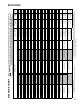
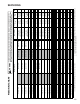
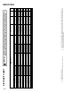
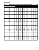
5. Compare the hi-pressure reading to the "Required Liquid
Line Temperature" chart (page 108). Find the hi-pres-
sure value on the left column. Follow that line right to the
column under the design subcooling value. Where the
two intersect is the required liquid line temperature.
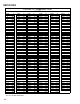
Alternately you can convert the liquid line pressure gauge
reading to temperature by finding the gauge reading in
Temperature - Pressure Chart and reading to the left, find
the temperature in the °F. Column.
6. The difference between the thermometer reading and
pressure to temperature conversion is the amount of
subcooling.
Add charge to raise subcooling. Recover charge to lower
subcooling.
Subcooling Formula = Sat. Liquid Temp. - Liquid Line
Temp.
EXAMPLE:
a. Liquid Line Pressure = 417
b. Corresponding Temp. °F. = 120°
c. Thermometer on Liquid line = 109°F.
To obtain the amount of subcooling subtract 109°F from
120°F.
The difference is 11° subcooling. See the specification sheet
or technical information manual for the design subcooling
range for your unit.
S-109A TWO SPEED APPLICATION
Run the remote on low stage cooling for 10 minutes until
refrigerant pressures stabilize. Follow the guidelines and
methods below to check unit operation and ensure that the
refrigerant charge is within limits. Charge the unit on low
stage.
1. Purge gauge lines. Connect service gauge manifold to
base-valve service ports. Run system at least 10 minutes
to allow pressure to stabilize.
2. For best results, temporarily install a thermometer on the
liquid line at the liquid line service valve and 4-6" from the
compressor on the suction line. Ensure the thermometer
makes adequate contact and is insulated for best
possible readings. Use liquid line temperature to deter-
mine sub-cooling and vapor temperature to determine
superheat.