
Installation guide
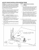
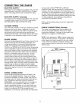


CONNECTING THE RANGE
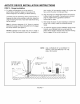
FIGURE 6
3-Wire Service Cord or Conduit Installation
1. Insure that the copper ground strap IS CONNECTED
between the middle post of the main terminal
connection block and the range chassis.
2. If bare copper or aluminum wiring is used, attach
adapter lugs as shown in figure 6. (See Bare Wire
Connection). Torque specifications are shown below.
3. The middle wire of the service cord or ground lead of
3-wire conduit MUST connect to the neutral (middle)
post of the main terminal block. The other two wires of
the service cord or conduit connect to the outside
posts of the main terminal connection block. Polarity is
unimportant. If using bare wire, attach wire to
appropriate lug as shown. Torque specifications are
shown below.
4. An appropriate strain relief for service cord or conduit
MUST be attached to the conduit plate.
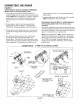
ACCEPTABLE - 3 WIRE PLUG INSTALLATION
CONDUIT
PLATE _ io.14 20 IE-LB
8 25 IE-LB
,; ALTERNATIVE INSTAllATION
,,>'_ FOR USE WITH CONDUIT. _
REMOVE BRACKET.FLIP /,/./_._'_/ ,_
& RE-ATTACH WITH SMALL ////'_\_ \L ///_
Ol
OUTLET RECEPTACLETO BE -_j
ROTATED AS SHOWN IF NOT _/ L'/
WOUNTED FLUSH FLUSH TO WALL "--
TO WALL
,.-" "-. BARF WIRF CONNECTION
I"
/
MAIN TERMINAL /
CONNECTION BLOCK 1
/ RED
MIDDLE WIRE OF WHITE
SERVICE CORD /.
OR CONDu(T ADAPTER
LUGS LOCATED
GROUNDING STRAP IN LITERATURE KIT BLACK
CONNECTED AT
FACTORY BAR[ W] RF TOROUF SPFC I F ICAT IONS
STRAIN
RELIEF LUG ATTA_H[D TO TERMINAL OLO_K - 20 IN-LB
WIREA_G
FIGURE 6
-6-