
Installation guide
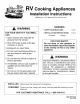


For RV Cooktops
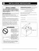
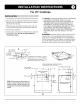
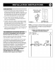
1. Cut opening in accordance with diagram shown below.
2. Align the 3/8" gas supply line with the hole provided in
burner box so it will slide into place when the range is
placed into the opening.
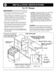
3. Place the range in position and fasten down with four
wood screws through holes provided in the side trim.
4. Connect gas supply line.
5. Check all gas connections for leaks with non corrosive
leak detection fluid. Do not use open flames for
checking gas leaks.
,
CAUTION: LIQUIFIED PETROLEUM (L.P.)/PROPANE
GAS SUPPLY LINE MUST HAVE A L.P. GAS
PRESSURE REGULATOR. INLET PRESSURE TO
THIS APPLIANCE SHOULD BE REDUCED TO A
MAXIMUM OF 14 INCHES WATER COLUMN (0.5
P.S.I.) INLET PRESSURES IN EXCESS OF 0.5 P.S.I.
CAN DAMAGE THE APPLIANCE PRESSURE
REGULATOR AND OTHER GAS COMPONENTS IN
THIS APPLIANCE AND CAN RESULT IN A GAS
LEAK.
WARNING: Porcelain enamel is glass which has been
fused to metal. It is thoroughly inspected and will give
good service if carefully handled, but it is breakable and
cannot be guaranteed. Like all glass or porcelain articles,
we cannot replace enamel parts that are damaged after
delivery to carriers except at customer's expense.
€,
Min. Vertical _ _, 18 9/16"
Back Wall 7/8" ! / *"t
1 _2_:di!!° oPsh!_a !i: !h!!_: sd! r_flS_'!n I
require radius return to trim of range.
-1-
4 1/2"
Minimum clearances zero from intergral
casing spacers below countertop.
J
q-
_-al"-I 7 ,r
r
NOTE:Clearancespacesshallbeframedin or 20 1/2' _, ._
guardedto preventstoragespacewithin the
clearancespecified.Cabinetenclosuresshall
bedesignedto preventdraftsthatwillaffectpilot
stability.
Min. Distance
to side wall 1 1/16" --'-I _ 21 3/8"
1
i
Dottedline indicates
.-..L top t,rim ,,__--_
Front Cut-out 4 3/8"
i I
i
i
i
I
i
i
I
.,,,._1 1/16"
2 !14"
" Pipe
Opening
Min. distance to back wall
-.--- , tI
18 9/16'----,,.- 17/8
7/16 -1
-7'-- --fm-.
- -[ Top Trim -
Overlap
Range to be supported
on countertop only
I
I
L
I
¢__
t
4 1/2"
1