
Installation guide


For RV Ranges
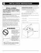
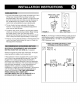
1. Cut opening as shown below (range can be suspended
from top flange; no other support is necessary.)
2. Range equipped with a 120 volt light in the oven will
require the installation of a 120V three prong grounded
receptacle directly behind the range (for correct
location see sketch below.) On range with BX cable
and marked for 12 volt DC power supply connect 12
volt DC power to the tagged wires.
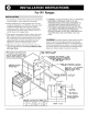
3. Place range in opening and fasten in place. Six screw
holes that are provided are located at points AA and
BB. A minimum of four screws must be used to fasten
range. Recreational vehicle manufacturers may use
appropriate holes as found necessary to suit the
application. Use No. 8 flat head wood screws.
4. Make gas connections and check for leaks with non
corrosive leak detection fluid. Do not check for leaks
with open flame.
,
CAUTION: LIQUIFIED PETROLEUM (L.P.)/PROPANE
GAS SUPPLY LINE MUST HAVE A L.P. GAS
PRESSURE REGULATOR. INLET PRESSURE TO
THIS APPLIANCE SHOULD BE REDUCED TO A
MAXIMUM OF 14 INCHES WATER COLUMN (0.5
P.S.I.) INLET PRESSURES IN EXCESS OF 0.5 P.S.I.
CAN DAMAGE THE APPLIANCE PRESSURE
REGULATOR AND OTHER GAS COMPONENTS IN
THIS APPLIANCE AND CAN RESULT IN A GAS
LEAK.
WARNING: Porcelain enamel is glass which has been
fused to metal. It is thoroughly inspected and will give
good service if carefully handled, but it is breakable and
cannot be guaranteed. Like all glass or porcelain articles,
we cannot replace enamel parts that are damaged after
delivery to carriers except at customer's expense.
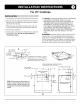
NOTE:Clearancespacesshallbeframed
in or guardedto preventstorage space
within the clearance specified. Cabinet
enclosuresshall be designedto
draftsthatwill affectpilotstability.
18
DIMENION IS FROM
FRONT FACE OF CABINET.
F COUNTERTOP HAS OVERHANG, IT MUST
BE NOTCHED TO SUIT THIS DIMENION.
COUNTERTOP OVERHANG IN EXCESS OF
1" WILL REQUIRE RADIUS RETURN
TO TRIM OF RANGE.
DIMENSION IS
FACE OF CABINET
TO REAR WALL.
21 7/
7/16-
SEE CHART
"CUTOUT HT"
7 8"
THE COUNTERTOP, R/ARt MIN.
DISTANCE TO VERTICLE WALL.
NOTE: MIN. 1 1/2" CLAERANCE
REQUIRFD FOR 16 SERIES
WHEN M,,GIC CHEF BIFOLD
COVER IS USED.
E THE COUNTERTOP, I 1/2" MIN.
DISTANCE TO VERTICLE SIDE WALL.
BB
L"
1"
MODEL CUTOUT HT. PIPE LOC.
16
MAC GROUNDED
3-PRONG RECEPTACLE
(IF REQUIRED)
16 3/8" 1 7/8"
FRONT Vl EW
22 21 13/16" 2 5/8"