TECHNICAL INFORMATION MANUAL AMH8 39" 80% Gas Furnace Model numbers listed on page 3. 80% AFUE, Two-Stage (Convertible), Mult-Speed, Upflow/Horizontal • Refer to Service Manual RS6610004 for installation, operation, and troubleshooting information. • All safety information must be followed as provided in the Service Manual. • Refer to the appropriate Parts Catalog for part number information. ® C This manual is to be used by qualified, professionally trained HVAC technicians only.
PRODUCT IDENTIFICATION The model and manufacturing number are used for positive identification of component parts used in manufacturing. Please use these numbers when requesting service or parts information.
PRODUCT IDENTIFICATION The model and manufacturing number are used for positive identification of component parts used in manufacturing. Please use these numbers when requesting service or parts information.
PRODUCT DESIGN General Operation The AMH8 furnaces are equipped with an electronic ignition device used to light the burners and an induced draft blower to exhaust combustion products. An interlock switch prevents furnace operation if the blower door is not in place. Keep the blower access door in place except for inspection and maintenance. This furnace is also equipped with a self-diagnosing electronic control module.
PRODUCT DESIGN Accessibility Clearances (Minimum) High Altitude Derate Unobstructed front clearance of 24" for servicing is recommended. When this furnace is installed at high altitude, the appropriate High Altitude orifice kit must be installed. This is required due to the natural reduction in the density of both the gas fuel and combustion air as altitude increases. The kit will provide the proper design certified input rate within the specified altitude range.
COMPONENT IDENTIFICATION Primary Limit Pressure Switch Flue Pipe Connection Gas Line Entrance (Alternate) Gas Line Entrance Induced Draft Blower Rollout Limit Blower Door Interlock Switch Inshot Burner Gas Manifold Circulator Blower Junction Box Transformer Integrated Control Module Upflow/Horizontal 1 Gas Valve 10 Induced Draft Blower 2 Gas Line Entrance (Alternate) 11 Blower Door Interlock Switch 3 Pressure Switch(es) 12 Integrated Control Module 4 Gas Manifold 5 Rollout Limit 13 Transf
PRODUCT DIMENSIONS AMH8 A L T . V E N T L O C A T IO N 4 7 /1 6 " 3 1 /4 " 1 5 /1 6 " 1 9 5 /8 " A 2 1 /1 6 " 1 5 /1 6 " B A L T . V E N T L O C A T IO N 3 1 /4 " 3 1 /8 " 8 " 9 5 /1 6 " 1 2 3 /1 6 " A L T . G A S IN L E T 39” C G A S L O C A T IO N H IG H V O L T A G E IN L E T L O W 2 7 1 /1 6 " 2 6 1 /2 " 1 4 3 /1 6 " 1 4 3 /1 6 " V O L T A G E 28” D 1 3 /8 " A L T . H IG H V O L T A G E A L T . L O W V O L T A G E 1 3 /8 " UNITS A B AMH80453AN** AMH80703AN** 14 12.
PRODUCT DESIGN PRESSURE SWITCH TRIP POINTS AND USAGE CHART PRESSURE SWITCH TRIP POINTS AND USAGE CHART SQUARE NOSE TRIP POINT ID BLOWER PRESSURE SWITCH ROUND NOSE TRIP POINT ID BLOWER PRESSURE SWITCH MODEL ID BLOWER PRESSURE SWITCH PART # MODEL ID BLOWER PRESSURE SWITCH PART # AMH80453AN** -0.60 B1370142 AMH80453AN** -0.60 B1370142 AMH80703AN** -0.60 B1370142 AMH80703AN** -0.60 B1370142 AMH80704BN** -0.60 B1370142 AMH80704BN** -0.47 B1370176 AMH80903BN** -0.
PRODUCT DESIGN Coil Matches: A large array of Amana® brand coils are available for use with the AMH8 furnaces, in either upflow or horizontal applications. These coils are available in both cased and uncased models, with or without a TXV expansion device. These new 80% furnaces match up with the existing Amana® brand coils as shown in the chart below.
PRODUCT DESIGN Thermostats: The following Amana® brand Thermostats are suggested for use with the AMH8 Furnace Models: THERMOSTATS Thermostat Mech./Digital Programmable Cool Heat CHT-18-60 Mechanical Yes Yes Yes CH70TG Digital No Yes Yes CHSATG Mechanical Yes Yes Yes H20TWR Mechanical Yes No Yes Filters: Filters are required with this furnace and must be provided by the installer. The filters used must comply with UL900 or CAN/ULCS111 standards.
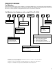
PRODUCT DESIGN TwinComfort™ Configuration & Operation TwinComfort™ This furnace is capable of the following heating modes: • Single Stage (Factory Setting) • Modified Two-Stage > Fixed 5-Min. Low Stage > Auto Time (1-12 Min.) Low Stage To change from the factory single-stage operation, adjust the dipswitches on the ignition control as follows: OFF ON MODE DIP SWITCH MODE 5 MIN. FIXED 2ND STAGE DELAY DIPSWITCH AUTO Note: This furnace is designed to be used with a single-stage room thermosat.
AMH81155CN* 90,000 90,000 90,000 115,000 140,000 72,000 72,000 72,000 92,000 112,000 Output, LP (BTUH) 32,000 48,000 48,000 64,000 64,000 64,000 80,000 96,000 A.F.U.E. 80.0% 80.0% 80.0% 80.0% 80.0% 80.0% 80.0% 80.0% 0.20 - 0.50 0.20 - 0.50 0.20 - 0.50 0.20 - 0.50 0.20 - 0.50 0.20 - 0.50 0.20 - 0.50 0.20 - 0.50 25 - 55 25 -55 20 - 50 30 - 60 35 - 65 35 - 65 35 - 65 40 - 70 Pressure Switch Trip Point (" w.c.) -0.60 -0.60 -0.60 -0.60 -0.60 -0.70 -0.70 -1.
BLOWER PERFORMANCE SPECIFICATIONS BLOWER PERFORMANCE (CFM & Temperature Rise vs. External Static Pressure) Model ( Heating Speed As Shipped ) Motor Speed EXTERNAL STATIC PRESSURE (Inches Water Column) Tons AC at 0.5" ESP 0.1 0.2 0.3 0.4 0.5 0.6 0.7 0.8 CFM RISE CFM RISE CFM RISE CFM RISE CFM RISE CFM CFM CFM HIGH 3.0 1555 --- 1511 --- 1459 --- 1392 --- 1344 25 1279 1201 1120 AMH80453AN** MED 2.
10 20 30 40 50 60 70 30 80 90 100 40 50 60 700 600 CFM 90 100 2000 2200 2400 CFM 1800 1600 1400 OUTPUT BTU/HR x 1000 80 1200 1100 1000 900 70 800 FORMULAS 110 120 130 140 BTU OUTPUT = CFM x 1.08 x RISE BTU OUTPUT ÷ CFM RISE = 1.
WIRING DIAGRAMS AMH8 WARNING:DISCONNECT POWER BEFORE SERVICING.WIRING TO UNIT MUST BE PROPERLY POLARIZED AND GROUNDED.
SCHEMATICS HIGH VOLTAGE! DISCONNECT ALL POWER BEFORE SERVICING OR INSTALLING THIS UNIT. MULTIPLE POWER SOURCES MAY BE PRESENT. FAILURE TO DO SO MAY CAUSE PROPERTY DAMAGE, PERSONAL INJURY OR DEATH. CIRCULATOR BLOWER HI COOL HEAT K2 ELECTRONIC AIR CLEANER LO HEAT CIR PARK NEU EAC INDUCER EAC NEU IND R K2 K3 RO2 RO1 K6 K3 ROLLOUT SWITCH TH K7 K1 XFMR HOT 24 VAC .