
Specifications


187 Rev. 3
SERVICING
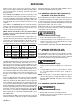
Compressor Serial Number Identification
COPELAND COMPRESSOR
TECUMSEH COMPRESSOR
BRISTOL COMPRESSOR
Motor Shift Year Month Serial No.
Month Serial No.
Serial No.
Year
Year
Day
Day of
Year
123456
123456
123456
E93J
T: 93C22
93291
G
.
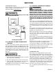
S-18 TESTING CRANKCASE HEATER
The crankcase heater must be energized a minimum of
four (4) hours before the condensing unit is operated.
Crankcase heaters are used to prevent migration or accumu-
lation of refrigerant in the compressor crankcase during the
off cycles and prevents liquid slugging or oil pumping on start
up.
A crankcase heater will not prevent compressor damage due
to a floodback or over charge condition.
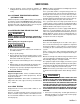
WARNING
Disconnect Electrical Power Supply:
1. Disconnect the heater lead in wires.
2. Using an ohmmeter, check heater continuity - should
test continuous, if not, replace.
NOTE: The positive temperature coefficient crankcase heater
is a 40 watt 265 voltage heater. The cool resistance of the
heater will be approximately 1800 ohms. The resistance will
become greater as the temperature of the compressor shell
increases.
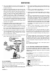
S-18 BBA/BBC CONTROL BOARD OPERATION
The BBA control board contains a relay that is operated based
on inputs from the room thermostat and thermistor. The relay
and therefore the blower is controlled per the following table.
Input Control Board Action
"G" on Relay energized instantly
"G" off Relay de-energized instantly
"Y" on Relay energized instantly
"Y" off
while "O" has
been on
Relay de-energized after supply air rises
above 65°F or 45 seconds, whichever is
shorter.
"Y" off
no "O"
Relay de-energizes after supply air rises
above 85°F or 45 seconds, whichever is
shorter.
Thermistor
Error
Relay energized until thermistor
operation is restored. Blower runs
continuously.
Supply Air
> 170°
Relay energized until supply air is
< 85°F.
"W2" or
"E" on
Relay energized instantly
"W2" or
"E" off
Relay de-energized instantly
Both the BBA and BBC control boards have an LED for indi-
cating operating status. The following table shows the codes
that may be displayed by the LED.
LED SIGNAL
ON TIME OFF TIME
Normal Operation 1/2 second 1/2 second
Thermistor and/or
Board Error
2 Flashes 3 seconds
Thermistor Error 4 Flashes 3 seconds
System Error 6 Flashes 3 seconds
Control Board
Malfunction
Continuous None
MODE
If the LED indicates a continuous 1/2 second on, 1/2 sec-
ond off flash code, then the control is in a normal operating
mode and no adjustments need be made.
If the LED indicates 2 flashes (thermistor and/or board error)
then the thermistor connections should be verified first. At
70°F the resistance of the thermistor should be 40 KW (as
temperature increases, resistance decreases). The resistance
should be checked between the terminations of the thermistor
leads at the control board, making sure that the terminals
are securely attached insuring a good connection. If the re-
sistance is out of range false signals will be sent to the con-
trol board, thus causing improper operation of the unit. In
that case, the thermistor must be replaced. If, however, the
resistance is correct, then the control board has malfunc-
tioned and must be replaced.
If the LED indicates 4 flashes (thermistor error) then the re-
sistance should be checked between the terminations of the
thermistor leads at the control board, making sure that the
terminals are securely attached insuring a good connection.