
Operating instructions


9
5. Defrost Control - The defrost control provides time/ tem-
perature initiation and termination of the defrost cycle.
6. Loss Of Charge Protector - The control opens from its
normally closed position to open the compressor contactor
should the system lose its refrigerant charge.
7. Outdoor Thermostats - These optional controls are used
to prevent full electric heater operation at varying outdoor
ambient (-17.8 to 7.2°C). They are normally open above
their set points and closed below to permit
staging of in-
door supplemental heater operation.
8. Reversing Valve Coil - This coil is activated by the ther-
mostat (system switch) during cooling only and during
defrost. It positions the reversing valve pilot valve for cool-
ing operation.
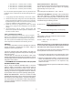
OPERATION:
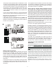
In operation the power to the circuit board is controlled by a
temperature sensor which is clamped to a return bend on the
outdoor coil. Timing periods of 30, 60, or 90 minutes may be
selected by connecting the circuit board jumper wire to 30,
60, 90 respectively.
Accumulation of time for the timing period selected starts
when the sensor closes (approximately -2.2°C) and when the
wall thermostat is calling for heat. At the end of the timing period,
a defrost cycle will be initiated provided the sensor remains
closed.
When the sensor opens (approximately 18.3°C), the defrost
cycle is terminated. If the defrost cycle is not terminated due to
the sensor temperature, a 10 minute override interrupts the
defrost period.
SUGGESTED FIELD TESTING / TROUBLE SHOOTING
A. Run unit in heat mode.
B. Check unit for proper charge. Note: Bands of frost indi-
cate low refrigerant charge
C. Shut off power to unit.
D. Disconnect outdoor fan by removing the purple lead from
“DF2” on defrost control.
E. Restart unit and allow frost to accumulate.
F. After a few minutes of operation, the defrost thermostat
should close. To verify this, check for 24 volts between
“DFT” and “C” on board. If the temperature at the ther-
mostat is less than -2.2°C and the thermostat is open,
replace the thermostat as it is defective.
G. When the defrost thermostat has closed, short the “test”
pins on the board until the reversing valve shifts, indi-
cating defrost. This could take up to 21 seconds de-
pending on what timing period the board is set on. After
defrost initiation, the short must instantly be removed or
the defrost period will only last 2.3 seconds.
H. After the defrost has terminated, check the defrost ther-
mostat for 24 volts between “DFT” and “C”. The reading
should indicate 0 volts (open sensor).
I. Shut off power to unit.
J. Replace outdoor fan motor lead and turn on power.
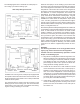
OPERATION - GENERAL
EXPLANATION AND GUIDANCE
The heat pump is a relatively simple device. It operates exactly
as a Summer Air Conditioning unit when it is on the cooling
cycle. Therefore, all the charts and data for service that apply to
summer air conditioning apply to the heat pump when it is on
the cooling cycle, and most apply on the heating cycle except
that “condenser” becomes “evaporator”, “evaporator” becomes
“condenser” and “cooling” becomes “heating”.
When the heat pump is on the heating cycle, it is necessary
to redirect the refrigerant flow through the refrigerant circuit
external to the compressor. This is accomplished with a
reversing valve. Thus, the hot discharge vapor from the
compressor is directed to the inside coil (evaporator on the
cooling cycle) where the heat is removed, and the vapor
condenses into liquid. It then goes through a capillary tube, or
expansion valve, to the outside coil (condenser on the cooling
cycle) where the liquid is evaporated, and vapor goes to the
compressor.
When the solenoid valve is operated either from heating to
cooling or vice versa, it moves the pilot valve, thus putting
suction pressure (low pressure) on one side of the piston of
the reversing valve, and since discharge pressure (high pres-
sure) is on the other side of the piston, the piston slides to the
low pressure side and reverses the flow of the refrigerant in
the circuit.